
Fastener Inspection Standards: Acceptance Criteria for Critical Bolted Joints

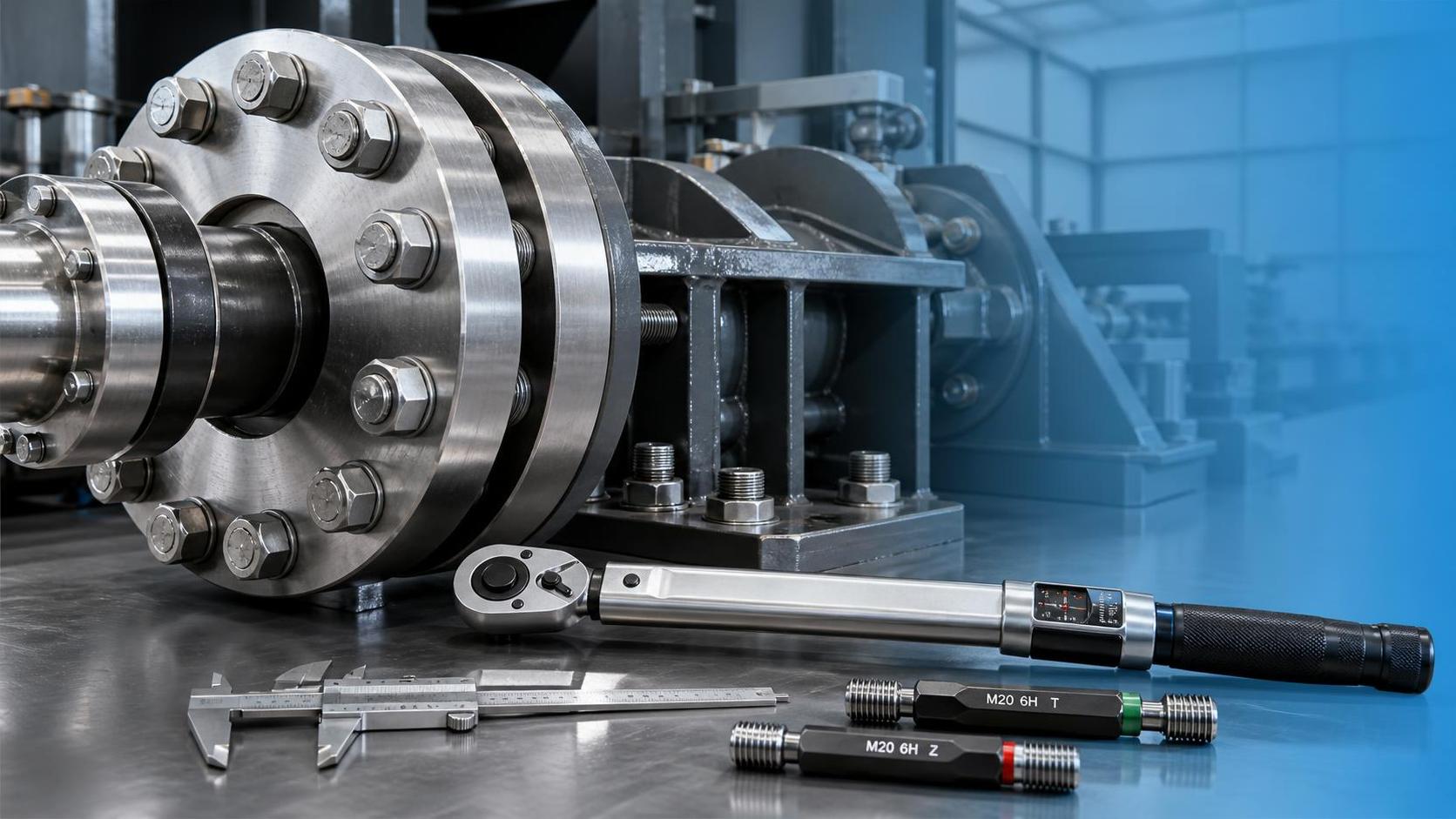
Fastener Inspection Standards: Acceptance Criteria for Critical Bolted Joints
Fastener inspection standards provide the foundation for safe, reliable critical bolted joints in industrial equipment, structures, pressure-containing systems, and production machinery. For quality and safety teams, the task is not simply to decide whether a bolt “looks acceptable.” A critical joint must be evaluated as a system: bolt, nut, washer, mating materials, holes, coating, lubrication, installation method, and the required clamping force all interact.
This distinction matters because many failures begin with a component that passed a basic receiving check but was unsuitable for its actual service condition. A bolt may have the correct diameter yet the wrong property class. A nut may fit the thread but not provide the required engagement. A torque record may exist, while the achieved preload remains uncertain because friction changed after coating or lubrication. Effective fastener inspection standards therefore connect material verification, dimensional control, installation quality, and traceable records.
The governing acceptance criteria should always come from the approved engineering drawing, project specification, applicable product standard, and assembly procedure. Standards such as ISO 898-1 for mechanical properties of carbon and alloy steel bolts, ISO 3506 for corrosion-resistant stainless fasteners, ASTM F3125 for certain structural bolt assemblies, ASTM F606/F606M for mechanical testing, ASME PCC-1 for pressure-boundary bolted flange joint assembly, and the RCSC Specification for structural joints may be relevant in particular applications. None should be applied automatically outside its scope.
Start by Defining What Makes the Joint Critical
Not every fastener needs the same inspection intensity. A cover-panel screw and a bolt retaining a rotating machine assembly should not be controlled in the same way. Critical bolted joints are commonly those where loss of clamp load, bolt fracture, leakage, joint slip, or incorrect assembly could create a safety hazard, unplanned shutdown, environmental release, or serious equipment damage.
Examples may include structural connections, lifting equipment, pressure flanges, pipeline supports, safety guards, electrical bus connections, high-vibration machine bases, tooling clamps, and fasteners used in pneumatic or hydraulic equipment. The actual classification should be established by the design authority or site risk process. Once a joint is designated critical, inspection plans should state what is checked, when it is checked, who is authorized to accept it, and what records must be retained.
A practical inspection plan separates three questions that are often mixed together: Is the fastener conforming? Is the joint prepared correctly? Was the specified assembly condition achieved? Passing one question does not answer the other two.
Receiving Inspection: Confirm Identity Before Condition
At receipt, the most important control is positive identification. Inspectors should verify that the delivered bolts, screws, nuts, washers, anchors, or studs match the approved bill of materials and purchase specification. This normally includes nominal size, thread designation and pitch, length, head style, material or strength grade, finish, coating, and any required manufacturer markings.
For high-strength or safety-sensitive fasteners, lot traceability is especially important. Packaging labels, certificates where contractually required, heat or lot numbers, and marking systems should be reviewed against the project requirement. A certificate should support traceability; it should not replace physical inspection. Mixed lots, damaged labels, or loose fasteners transferred into unmarked bins can make later verification difficult or impossible.
Visual condition is the next screen. Reject or quarantine components showing obvious corrosion, deep gouges, distorted threads, cracked heads, burrs that prevent seating, damaged drive recesses, coating flaking, or contamination that could affect installation. Light cosmetic variation is not automatically a rejection, but any condition that changes fit, bearing contact, friction, corrosion performance, or material section needs engineering review.
What visual inspection cannot prove
A visual examination cannot verify tensile strength, proof load, hardness, chemical composition, hydrogen embrittlement risk, or actual preload capacity. Markings can be incomplete, counterfeit, or incorrectly interpreted. Where the risk level or contract requires it, verification may involve review of test documentation, independent laboratory testing, hardness checks, dimensional gauges, or other controls approved by the responsible engineer. Sampling frequency should be defined in the quality plan rather than selected casually at the receiving dock.
Dimensional Acceptance Is About Fit and Load Path
Dimensional inspection is sometimes treated as a routine measurement exercise, but for critical joints it directly affects load transfer. The bolt diameter, shank length, thread length, grip length, nut height, washer dimensions, and hole geometry must suit the joint design. A bolt that bottoms out before clamping the parts, for example, can show an apparently tight nut while producing little useful clamp load.
Thread quality should be checked with suitable go/no-go gauges or equivalent approved methods when required by the inspection plan. Cross-threading, flattened crests, torn threads, plating buildup, and thread damage from handling can cause false torque readings or prevent full engagement. Thread engagement requirements vary by design, material, and loading direction. It is unsafe to rely on a generic rule when the drawing or assembly standard specifies a different minimum engagement condition.
Washer selection also deserves attention. Hardened washers, plain washers, locking devices, wedge-locking systems, or direct-tension indicators may be specified for particular joint types. Substituting a washer because it has the same inside diameter can alter bearing stress, friction, or the behavior of the tightening method. Components supplied as an engineered assembly should generally remain together unless the relevant specification permits otherwise.
The Joint Surface Often Determines the Result
Critical fastener inspection extends beyond the fastener itself. Inspect the clamped parts before installation: mating faces should be free from debris, paint buildup where prohibited, burrs, weld spatter, damaged coatings, and misalignment that prevents full contact. In a structural slip-critical connection or a flange joint, surface condition can be central to the joint’s design performance. In machinery, soft coatings or uneven surfaces may embed after tightening and reduce clamp load during early service.
Hole size, slot orientation, edge distance, and alignment should be checked against the drawing or applicable connection standard. Forcing a bolt through a misaligned hole can damage threads or introduce bending. Using an unapproved oversized hole, adding extra washers to compensate for a poor fit, or reaming holes without authorization may change the intended load path. These are engineering disposition issues, not field improvisations.
Tightening Acceptance: Torque Is a Method, Not a Guarantee
The purpose of tightening is usually to create adequate bolt tension and clamp force, not merely to reach a torque number. Torque is influenced by thread condition, lubricant, coating, nut bearing friction, washer condition, tool calibration, and installation speed. The same torque can produce materially different bolt tension when these variables change. This is why a torque value copied from an unrelated chart should never become the acceptance criterion for a critical joint.
The approved procedure may specify torque control, torque-angle tightening, turn-of-nut, direct tension indication, tensioning devices, hydraulic methods, or a documented combination of methods. Each has limits and verification needs. For example, torque-controlled tightening normally requires calibrated tools and a defined lubrication condition. Angle-controlled methods require a reliable snug-tight starting point and joint geometry that permits accurate rotation. Pressure flange assembly frequently requires controlled cross-pattern tightening in stages, with gasket condition and flange alignment considered alongside bolt loading.
Inspectors should verify the method actually used, not just the final appearance. Key acceptance evidence may include tool identification and calibration status, prescribed sequence, target settings, recorded final values where required, installer qualification, witness marks, and any post-installation verification called for by the procedure. Witness marks are useful for detecting later movement, but they do not independently demonstrate that the initial preload was correct.
Do not “re-torque” without a defined reason
A common response to uncertainty is to apply torque again during inspection. This can be misleading and, in some assemblies, harmful. Static friction after installation differs from running friction during tightening, and an additional torque application may not reveal actual bolt tension. It can also over-stress a fastener or disturb a joint that was assembled by a different controlled method. Any verification or retightening step should follow the applicable procedure and be documented as such.
Material, Coating, and Environmental Risks
Material compatibility deserves careful review in corrosive, high-temperature, low-temperature, electrically sensitive, or vibration-heavy environments. Stainless steel fasteners are not interchangeable with carbon steel fasteners simply because they resist visible corrosion. Their strength class, galling behavior, temperature performance, and galvanic interaction with the connected materials may differ. Likewise, zinc-plated, mechanically galvanized, hot-dip galvanized, phosphate-coated, and plain finishes create different dimensional and friction conditions.
Hydrogen embrittlement is a particularly serious concern for certain high-strength steel fasteners and some coating or cleaning processes. Inspection personnel should not attempt to diagnose it visually. The relevant specification, supplier controls, coating process requirements, and any project-specific restrictions should govern acceptance. If a fastener’s history is uncertain after replating, chemical stripping, overheating, or unauthorized rework, quarantine is usually more defensible than assuming it remains suitable.
Nonconformance Decisions Need Discipline
The right response to a nonconforming fastener is not always immediate scrapping, but it should never be casual acceptance. Segregate affected material, preserve lot information, identify the joint locations if installation has begun, and raise the issue through the approved nonconformance process. Engineering may determine that replacement, additional testing, controlled rework, or use-as-is disposition is appropriate. Quality personnel should not independently approve substitutions between grades, materials, coatings, or tightening methods.
This becomes especially important when procurement pressures encourage “equivalent” alternatives. Equivalence must be demonstrated against the actual joint requirements: mechanical properties, geometry, coating, service environment, certification needs, installation process, and applicable standard. A product catalog description alone is rarely enough evidence for a critical bolted connection.
Records That Support Safety and Future Maintenance
Good records make inspection findings usable after handover. At a minimum, critical-joint documentation should connect the joint location or assembly number to the fastener specification, lot or traceability information where required, inspection results, tightening procedure, tool status, date, and responsible personnel. Photographs may help clarify location or witness-mark condition, but they should supplement rather than replace measurable records.
For maintenance teams, the record should also state whether reuse is permitted. Many fasteners can be reused only under defined conditions; others, including some preloaded assemblies, prevailing-torque nuts, locking elements, or bolts that have entered a controlled yield-based tightening range, may have specific replacement rules. The manufacturer’s instructions and the governing assembly standard should take precedence over habit.
Across global supply chains, terminology, product markings, and standard references can vary between regions and suppliers. GHTN helps engineers, quality teams, distributors, and industrial buyers compare fastener knowledge with related tooling, electrical, mold, and pneumatic application requirements. The useful starting point is always the same: identify the exact joint function, establish the controlling standard and drawing requirements, then inspect the installed assembly—not just the bolt in isolation.
For any critical bolted joint, acceptance should be based on evidence that the correct components were used, the joint was properly prepared, and the approved installation method achieved its intended result. When any of those elements cannot be confirmed, the safest next step is to pause, retain traceability, and obtain an engineering decision before the equipment enters service.
Related News