

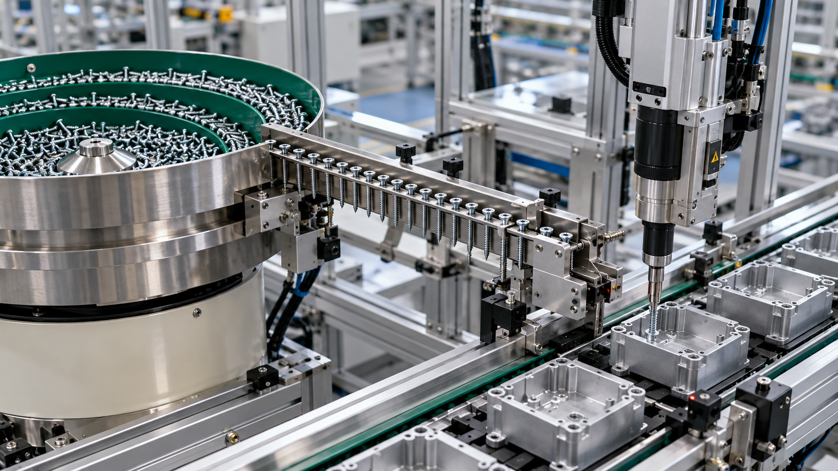
A fastening station can meet torque specifications and still constrain production when screws arrive misoriented, feeders jam, or replenishment repeatedly interrupts the assembly cycle.
For project managers selecting fasteners for automated assembly line applications, reliable integration starts with matching fastener geometry, coating, and dimensional consistency to feeding requirements.
The strongest approach treats the fastener, feeder, transfer mechanism, driver, and controls as one production system, with shared performance requirements and clearly assigned responsibilities.
Before approving equipment, establish whether that complete system can sustain the required output, recover predictably from faults, and accommodate normal variation in production fasteners.
Define the Feeding Requirement Before Selecting Equipment
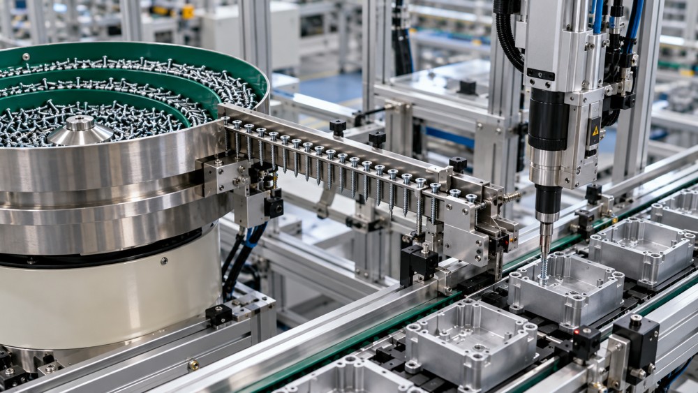
Start with the production requirement: target takt time, fasteners per assembly, product variants, shift pattern, and the output expected from each individual fastening station.
A line producing one assembly every twelve seconds with four screws requires twenty screws per minute on average, before accounting for interruptions or rejects.
That average does not describe the complete demand. A station inserting four screws rapidly may need a local buffer even when upstream feeding capacity appears sufficient.
Distinguish three measures: sustained feeder output, screw availability at the presentation point, and completed fastening cycles. A supplier’s maximum feed rate proves only one.
Define when each screw must be available relative to driver movement. Include transfer, confirmation, insertion, tightening, and any indexing that cannot occur in parallel.
Ask suppliers to demonstrate capacity with the specified fastener and delivery arrangement. A catalog rating based on another screw geometry cannot establish application performance.
Set capacity margin according to demand variation and recovery needs. A fixed percentage provides little protection unless the project understands where interruptions actually occur.
Which Fastener Features Create the Greatest Feeding Risk?
Fastener selection affects both joint performance and automation reliability. Freeze the joint requirements first, then assess whether the proposed geometry can be consistently handled.
Short screws with relatively wide heads may be challenging to orient or blow through tubing, but suitability depends on the feeder and transfer design.
Likewise, washers, captive elements, and unusual head shapes can require dedicated handling. Obtain application testing before accepting claims that a fastener is universally feedable.
Do not tighten every dimensional tolerance automatically. Identify the dimensions controlling orientation, separation, pickup, and joint function, then agree measurable limits with both suppliers.
Coating changes deserve particular attention because they can affect feeding friction and the torque–clamp force relationship. Review handling and joint validation together before approval.
Require representative production lots, including permitted dimensional and finish variation. Hand-selected samples can conceal problems that emerge immediately when bulk production material reaches the line.
Choose the Feeding Architecture Around the Application
Vibratory bowls often suit established, high-volume applications with stable fastener geometry. Their performance depends on track design, tooling condition, fill level, and operating settings.
Step feeders and other lifting systems may reduce agitation in suitable applications. Compare actual surface damage, noise, footprint, and orientation performance during supplier trials.
Flexible feeders with vision-guided picking can support product variety, but their suitability depends on presentation quality, recognition reliability, robot cycle time, and required output.
Magazine or tray presentation may be appropriate for delicate, unusual, or lower-volume fasteners. Include preparation labor and replenishment frequency when comparing total operating cost.
After orientation, choose between options such as blow feeding and pick-and-place delivery. Fastener geometry, access, cleanliness, travel distance, and driver layout influence that decision.
For pneumatic transfer, validate tube routing, bends, connections, and air conditions in the installed layout. A successful short-bench trial does not prove full-line delivery.
For pickup systems, check pickup confirmation, retention during movement, and access to the joint. Include robot travel and recovery movements in the demonstrated cycle.
Size Buffers to Protect Output Without Hiding Problems
A buffer separates short feeding interruptions from fastening demand. It provides recovery time, but cannot compensate indefinitely when average replenishment falls below average consumption.
Estimate usable buffer capacity by multiplying consumption rate by the interruption duration the station must tolerate. Then evaluate variation, physical constraints, and recovery behavior.
At twenty screws per minute, covering a thirty-second supply interruption requires ten usable screws. This calculation excludes additional allowance for uncertainty or inaccessible inventory.
Count only fasteners that remain available to the station during the interruption. Material upstream of a blocked escapement may offer no useful production protection.
Check refill behavior as carefully as buffer size. After an interruption, the feeder must replenish inventory while continuing to support the station’s ongoing demand.
Provide low-level warnings early enough for a normal operator response. Confirm that hopper replenishment can occur safely without introducing contamination or disrupting part orientation.
Avoid treating larger inventory as the default solution. Excess loading can increase part interaction, obscure recurring faults, and lengthen clearance or product-change procedures unnecessarily.
Make Controls Detect Problems Before They Become Line Stops
Controls should distinguish an empty hopper, failed orientation, blocked transfer, missing screw, unsuccessful pickup, and fastening failure. Each condition requires a different recovery response.
Agree the machine handshake before software development begins. Define requests, ready signals, screw-present confirmation, timeouts, fault states, reset conditions, and responsibility for each transition.
A transfer-complete signal does not necessarily prove that a screw reached the tool correctly. Locate confirmation where it establishes readiness for the next operation.
Use bounded automatic retries only where the machine can verify its state. Repeated feeding into an occupied path can turn a recoverable fault into damage.
Fastening results need separate verification. Depending on joint criticality, evaluate torque, angle, depth, or other process signals to identify missing, cross-threaded, or incompletely seated fasteners.
Log faults by category, duration, product variant, and relevant material lot. A single downtime total cannot distinguish poor fastener consistency from transfer or controls problems.
Design recovery around operator actions as well as machine logic. Clearly identify the obstruction location, safe clearance procedure, and checks required before production resumes.
Write Supplier Requirements That Close Integration Gaps
The purchasing specification should connect fastener characteristics with equipment performance. Separate documents without shared acceptance criteria often leave responsibility unclear when the integrated station underperforms.
Specify approved fastener drawings, critical dimensions, material and finish requirements, cleanliness expectations, packaging, and lot identification. Include the process for approving future supplier changes.
For equipment, document required sustained output, permitted interventions, buffer behavior, replenishment conditions, changeover requirements, maintenance access, and the production conditions under which performance will be measured.
Assign ownership for the interfaces between fastener supply, feeder tooling, transfer hardware, fastening equipment, and line controls. Record who investigates faults crossing those boundaries.
Require change notification for modifications affecting feedability or joint behavior. Examples include coating chemistry, lubrication, manufacturing tooling, packaging, and substitutions within an approved part family.
Include spare escapement components, wear parts, transfer tubing, sensors, and special setup tools in the support plan. Confirm availability against the project’s acceptable downtime.
Project managers should establish an integrated trial before final design approval. Discovering incompatibility then usually leaves more recovery options than discovering it during site commissioning.
Validate Sustained Production, Fault Recovery, and Changeovers
A short demonstration establishes basic feasibility. Production acceptance requires a defined test duration, representative operating conditions, and enough fastener consumption to expose recurring interruptions.
Use multiple production lots where available, approved product variants, realistic hopper levels, and normal replenishment. Include the actual transfer arrangement and specified utility conditions.
Measure completed assemblies, feeding-related downtime, interventions per defined quantity, replenishment interruptions, and recovery time. Record rejected assemblies separately so output figures remain meaningful.
Define metric denominators explicitly. “One jam per shift” means little without shift duration, screws consumed, operating conditions, and the time needed to restore production.
Test foreseeable faults deliberately under controlled procedures: empty supply, missing screw, interrupted transfer, and loss of utilities. Confirm detection, safe behavior, and restart logic.
Factory acceptance should demonstrate the agreed integrated configuration wherever practical. Site acceptance must confirm performance with installed routing, utilities, adjacent equipment, and normal staffing.
Complete operator training and changeover trials before handover. If only the supplier’s specialist can restore stable feeding, the production team has inherited unresolved dependence.
Compare Total Production Cost Before Approving the Investment
The lowest fastener price may increase total assembly cost if variation causes stoppages, sorting, rework, or additional inspection. Evaluate these costs using demonstrated performance.
Estimate feeding-related production loss from event frequency, average recovery time, and the line’s constrained output. Avoid counting losses twice when buffers absorb an interruption.
Include equipment, installation, commissioning, consumables, maintenance labor, utilities, changeovers, and inventory. Compare alternatives over a consistent operating period and an agreed production volume forecast.
A more expensive fastener or feeder can be justified when measured reductions in downtime and labor exceed its additional cost. Make those assumptions visible.
For high-mix lines, changeover time and adjustment repeatability may outweigh peak speed. For stable high-volume production, sustained availability and predictable wear may dominate economics.
Release the project when joint performance, feeding capability, controls, and operational support meet agreed criteria. Unresolved interface issues should have owners, deadlines, and closure evidence.
Build Reliability Into the System Before Launch
Selecting fasteners for automated assembly line projects requires coordinated decisions about the joint, part consistency, feeding architecture, controls, and the people responsible for keeping production running.
The practical approval question is whether representative production fasteners reach the tool reliably at the required rate, with manageable replenishment, maintenance, changeover, and fault recovery.
Define those conditions early and verify them through integrated testing. This gives project leaders a defensible investment decision and a clearer path to production readiness.