
Why industrial productivity stalls in stamping lines

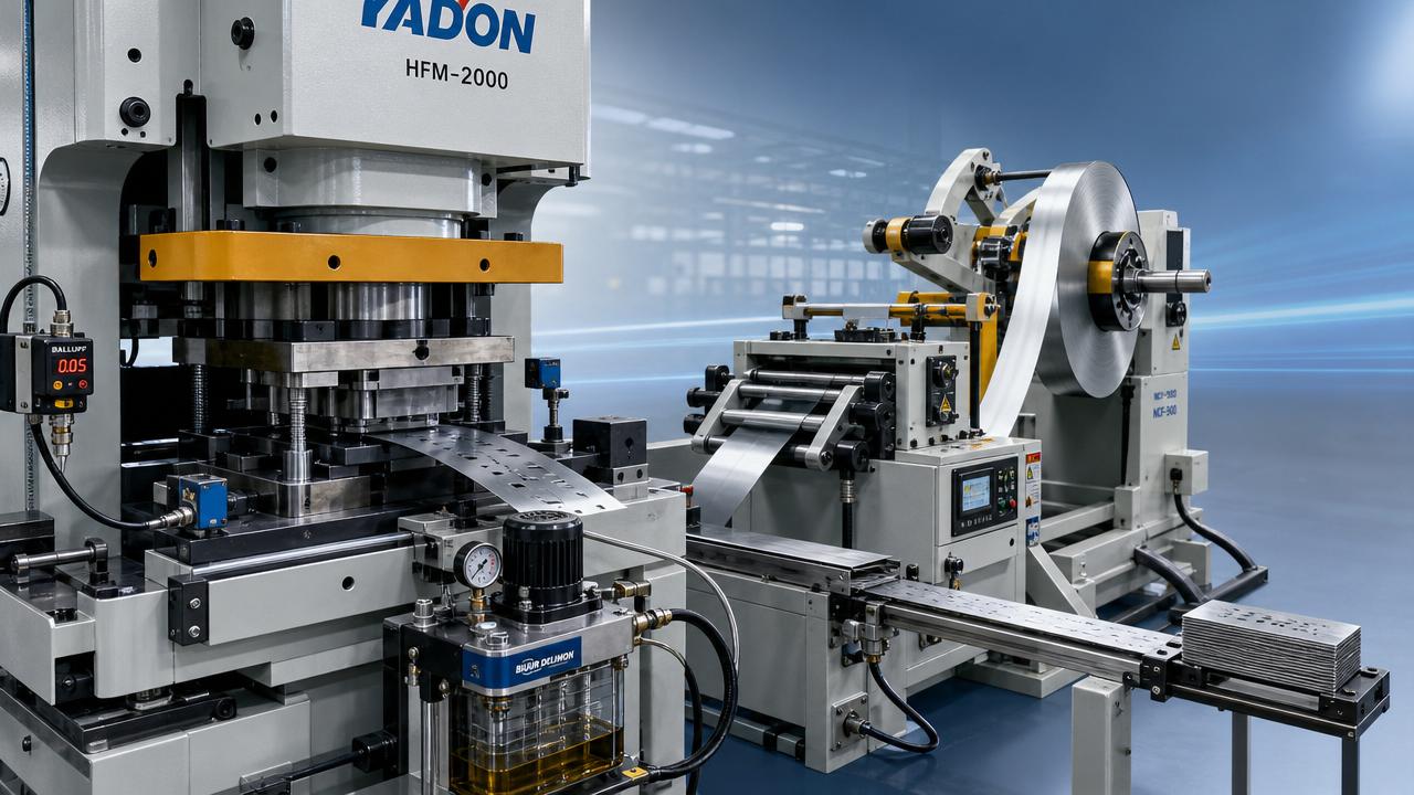
Industrial productivity often stalls in stamping lines not because of one major breakdown, but because small inefficiencies compound across tooling, material flow, press settings, and operator response. For users and line operators, understanding where these losses begin is the first step toward restoring output, improving consistency, and reducing costly downtime in high-demand manufacturing environments.
In real production, a line can appear busy while output still drops by 5% to 15% over a shift. Parts keep moving, presses keep cycling, and operators keep responding, yet overall industrial productivity fails to reach planned targets. This gap matters most in stamping environments where takt time is tight, changeovers are frequent, and even small deviations in die condition, feed accuracy, or coil quality can trigger scrap, minor stops, and operator intervention.
For operators, maintenance teams, and line users, the practical question is not only why a press stops. It is why the line underperforms long before a full stop happens. In stamping, the answer usually sits at the intersection of tooling wear, electrical response, pneumatic timing, lubrication control, and material handling discipline. That is where industrial productivity is either protected or lost.
Where industrial productivity leaks out of stamping lines
Most stamping losses are cumulative. A press line may lose only 3 seconds per cycle from misfeed checks, 8 minutes per shift from die cleaning, and another 1% to 2% from inconsistent strip progression. None of these issues looks dramatic in isolation, but together they can reduce usable output by dozens or even hundreds of parts per shift.
Tooling wear starts the chain reaction
Die condition is one of the fastest ways industrial productivity starts to slip. Punch edge wear, die clearance drift, guide pin play, and slug buildup can gradually increase burr height, part deformation, or stripping force. Operators often first see the symptom as unstable part ejection or extra noise, but the real cost appears later as slower speed, more inspections, and unplanned tool corrections.
In medium-to-high volume lines, even a burr increase of 0.03 mm to 0.08 mm may trigger customer quality concerns or force speed reduction. If die maintenance is delayed by 1 or 2 production runs, the line often compensates through manual adjustments rather than root-cause correction. That practice protects short-term output, but over time it damages industrial productivity by normalizing instability.
Typical tooling-related warning signs
- Press tonnage trend rising 5% to 10% without a planned material change
- More frequent part sticking, double hits, or inconsistent slug discharge
- Extra operator adjustments during the first 30 to 60 minutes after startup
- Scrap concentrated at one station rather than across the whole die
Material flow problems are often underestimated
Coil set, camber, edge wave, lubrication inconsistency, and feed roller contamination can all reduce line stability before anyone records a machine fault. In many facilities, operators spend 10 to 20 minutes per shift correcting strip alignment or clearing feed-related alarms. This does not always look like downtime in reports, but it directly weakens industrial productivity.
Material flow issues also create hidden quality variation. If feeder progression drifts by even ±0.10 mm to ±0.25 mm in a precision die, hole position, trim balance, or form repeatability can shift enough to increase inspection load. The line may still run, but not at the speed or confidence level required for stable industrial productivity.
The following table shows how common loss points appear on the shop floor and how operators can identify them early.
A useful pattern emerges here: the same four or five issues repeat across many stamping lines, regardless of sector. Automotive, appliance, electrical hardware, and industrial parts production all face similar loss mechanisms. That is why industrial productivity is best improved through disciplined control of fundamentals rather than only by adding more machine capacity.
Press settings and response timing matter more than many teams expect
Press speed, shut height, counterbalance pressure, and sensor windows need to match tooling condition and material behavior. If a line runs at 35 strokes per minute when the die is stable only at 28 to 30, alarms and part variation rise quickly. If the line runs too slowly, however, the operation loses planned capacity and may create extra handling time downstream.
Electrical and pneumatic components are equally important. Delays in valve actuation, weak connectors, inconsistent signal feedback, or poorly protected sensors often create intermittent faults. These are among the hardest losses to diagnose because they may appear only once every 200 to 500 cycles, yet they still erode industrial productivity through repeated stoppages and operator resets.
How operators can recover industrial productivity without waiting for a major overhaul
Improvement does not always begin with new equipment. In many stamping operations, 60% to 80% of recurring output loss can be reduced through better inspection discipline, faster feedback loops, and standard operating responses. Operators are central to this process because they see cycle irregularities before they become maintenance events.
Build a four-point daily control routine
A practical daily control routine should take 10 to 15 minutes at startup and 5 minutes during each scheduled check. The goal is not paperwork. The goal is to catch the earliest signs of output drift while the line is still recoverable.
- Verify tooling condition, slug clearance, and visible wear points before first run.
- Confirm feeder accuracy, strip alignment, and lubrication consistency on initial parts.
- Check sensor cleanliness, connector stability, and pneumatic response timing.
- Record abnormal sound, vibration, or part release behavior within the first 50 cycles.
This kind of routine supports industrial productivity because it converts operator observation into repeatable process control. Instead of reacting after a jam or quality hold, the line acts earlier. On many lines, one prevented misfeed event can save 20 to 40 minutes of recovery time, especially when die reset and part verification are required.
What should be logged every shift
- Actual strokes per minute versus planned rate
- Number of short stops under 5 minutes
- Scrap count by station or defect type
- Tool touch-up or cleaning interventions
- Material handling interruptions from decoiler to outfeed
Use threshold-based decisions instead of guesswork
Many lines lose industrial productivity because decisions are based on experience alone, not on agreed thresholds. Experience remains valuable, but it works best when tied to clear triggers. For example, if scrap exceeds 1.5% in a 2-hour window, or if the line records 3 misfeed alarms in 30 minutes, the team should switch from running adjustments to root-cause inspection.
Threshold-based control also helps communication across shifts. When the day team and night team use the same rules for speed reduction, die cleaning, or maintenance calls, output becomes more predictable. That consistency is a major factor in restoring industrial productivity over weeks and months, not just one shift.
The table below provides a practical response matrix that operators and supervisors can adapt to their own stamping lines.
The main advantage of this matrix is speed. It reduces hesitation and prevents overreliance on temporary fixes. For stamping teams under output pressure, fast and consistent decision-making is often the difference between one short interruption and a full shift of declining industrial productivity.
Improve changeovers to protect output all week
Many plants focus on runtime efficiency but overlook changeover losses. If a die change is planned for 25 minutes and regularly takes 40 to 50, weekly capacity drops sharply. In mixed-volume production, two extra 15-minute delays per day can remove more output than one moderate-speed improvement.
A better changeover process usually includes preset die height references, verified clamp points, labeled sensor cables, feeder setup sheets, and first-off inspection standards. These controls are simple, but they support industrial productivity by stabilizing the first 100 to 300 parts after each setup, where many defects and stops are created.
Component choices that quietly shape stamping performance
Industrial productivity in stamping lines depends not only on the press itself, but also on the reliability of smaller components. Fasteners, guide elements, sensors, pneumatic fittings, lubrication units, springs, and electrical interfaces form the hidden structure of line stability. When these components are poorly matched to load, cycle rate, contamination level, or maintenance reality, recurring losses follow.
Mechanical components must match cycle stress
Users sometimes treat guide elements, stripper bolts, die springs, and fastening systems as standard consumables. In reality, each one has a service effect. A component selected for moderate duty may perform poorly when exposed to 30 strokes per minute over 3 shifts, especially in environments with dust, oil mist, or off-center loads.
For example, if spring fatigue appears earlier than expected, stripping consistency changes, part release becomes unstable, and operators may reduce speed to compensate. That is a direct industrial productivity loss created by component mismatch, not by operator error alone.
Key selection checks for line users
- Confirm the expected cycle count per week and actual shock load range
- Review exposure to oil, fines, heat, and vibration near the die area
- Check whether replacement intervals are preventive or failure-driven
- Verify whether the component supports quick installation and repeatable positioning
Electrical and pneumatic reliability affect response speed
Sensor accuracy and valve response are critical where part detection, pilot timing, air blast, or ejection confirmation happen in narrow windows. A delay of milliseconds may sound minor, but at 25 to 40 strokes per minute, repeated lag increases the risk of false trips or missed actions. Over a full shift, those interruptions become a meaningful industrial productivity drain.
This is why many advanced users review connector sealing, cable routing, valve cycle life, and contamination resistance during procurement. Better components do not eliminate every fault, but they reduce the frequency of unstable signals and help the line maintain planned output with fewer manual resets.
Common operator mistakes that keep productivity low
Not every output loss comes from hardware. Some of the most persistent industrial productivity issues come from familiar but ineffective responses on the line. These habits often develop under delivery pressure, especially when teams are rewarded for keeping the press moving rather than stabilizing the process.
Running through early warnings
A light burr increase, occasional part hang-up, or one misfeed alarm may be dismissed as normal variation. If the team keeps running, however, the problem often grows into damaged tooling, more scrap, and a longer stoppage later. A 3-minute pause for inspection can prevent a 45-minute recovery event.
Using speed reduction as the only fix
Lowering strokes per minute is sometimes necessary, but it should not become the default answer. If a line repeatedly drops from 32 strokes per minute to 24 just to survive a shift, industrial productivity is already compromised. The underlying issue may be wear, material variability, feeder instability, or delayed maintenance, and none of those is solved by permanent slowdown.
Incomplete shift handover
When one shift fails to record where scrap started, which station was adjusted, or which alarm appeared twice, the next shift starts blind. This repeated loss of process memory is common in stamping plants and can quietly cost several percentage points of industrial productivity each week. Good handover should take 5 to 10 minutes and include rate, scrap, interventions, and unresolved risks.
A practical path forward for stamping teams and industrial buyers
Recovering industrial productivity in stamping lines requires both process discipline and dependable industrial components. Operators need clear thresholds, fast inspection routines, and better feedback from maintenance. Supervisors need visibility into short stops, scrap patterns, and changeover losses. Buyers need component and tooling decisions that support real cycle conditions, not only initial cost targets.
That broader view is especially important in complex manufacturing networks, where mechanical tools, electrical hardware, mold systems, and precision parts all interact. A reliable stamping line is rarely the result of one upgrade. More often, it comes from coordinated improvements across tool condition, feeder control, sensor reliability, lubrication practice, and operator response.
For organizations looking to strengthen line stability and reduce hidden losses, GHTN provides a practical perspective grounded in industrial components, precision tooling, and manufacturing logic. Whether you are reviewing die-related wear points, electrical compliance needs, pneumatic response risks, or sourcing criteria for better line support, the right technical insight can help turn unstable output into repeatable performance.
If your stamping operation is facing recurring short stops, inconsistent quality, or underused capacity, now is the time to review the root causes behind stalled industrial productivity. Contact us to discuss your application, get a tailored component or tooling perspective, and explore more solutions for stable, high-demand manufacturing.
Related News