

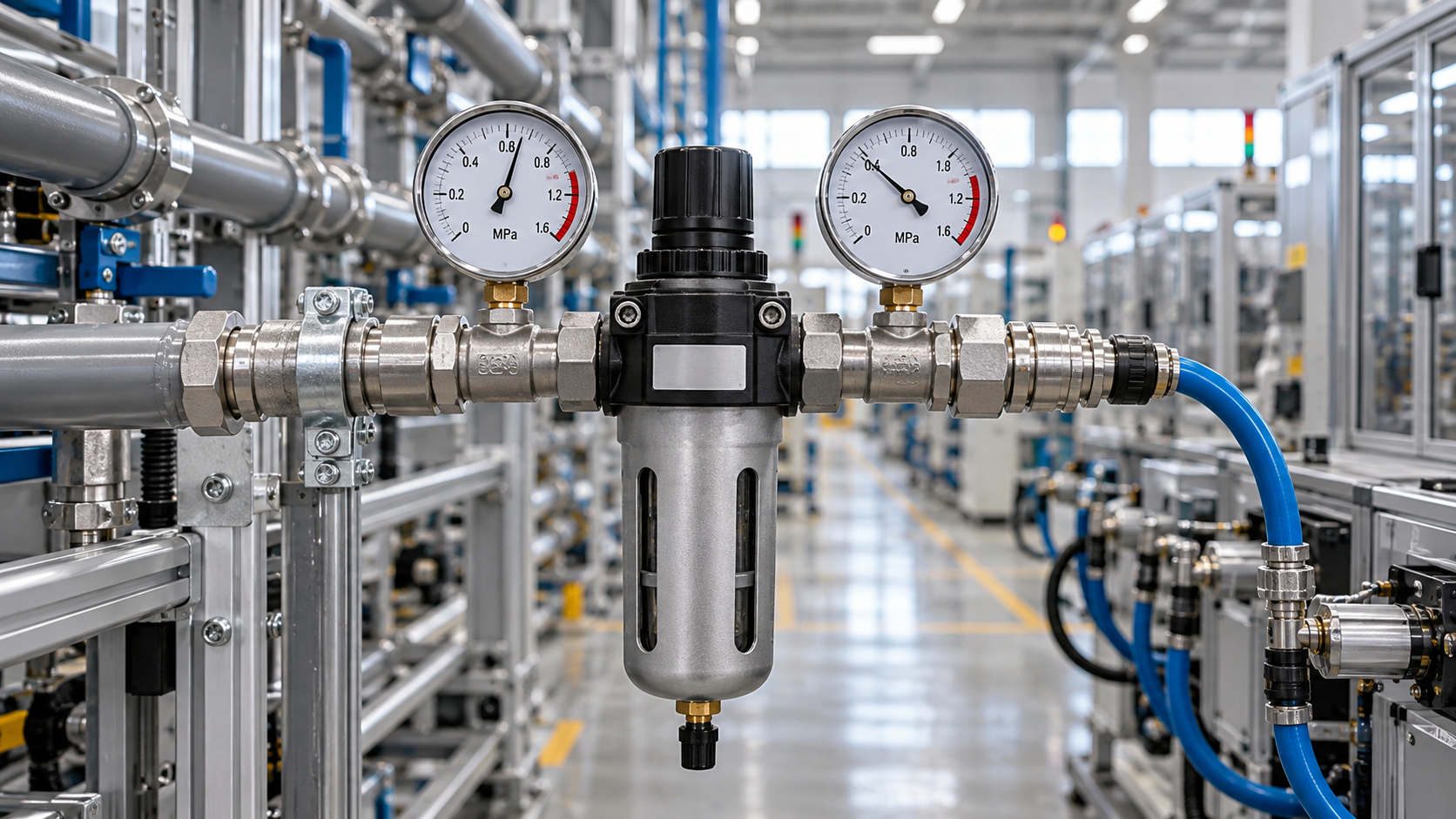
When pneumatic tools lose power or actuators slow down, raising compressor pressure may mask the fault while increasing energy use across the system.
For after-sales maintenance teams, effective air compressor pressure drop solutions start with locating pressure losses under operating flow, rather than simply adjusting the setpoint.
Clogged filters, undersized hoses, restrictive couplings, and overloaded dryers can all limit delivery. Normal pressure at an idle machine does not prove adequate supply.
Compare pressure at the compressor, treatment equipment, distribution piping, and machine inlet during the same operating event. Repair the largest avoidable loss first.
Where Should You Measure Pressure to Find the Restriction?
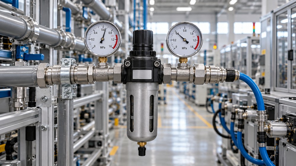
Start with the equipment complaint: identify which tool or actuator struggles, when it happens, and whether neighboring machines experience the same symptoms simultaneously.
Ask whether performance changed after maintenance, a hose replacement, added production equipment, or a new operating sequence. These details often narrow the investigation quickly.
Map the actual air path, including the receiver, dryer, filters, branch piping, isolation valves, regulator, couplings, hose, directional valve, and any machine-mounted treatment components.
Install suitable gauges or pressure transducers at accessible points along that path. Use instruments with appropriate pressure ratings, useful resolution, and reasonably matched accuracy.
Measure immediately upstream and downstream of suspected restrictions while the equipment operates. Simultaneous readings are preferable because compressor cycling can distort comparisons taken sequentially.
For short actuator cycles, use sensors and logging fast enough to capture the minimum pressure. A slowly responding gauge may hide a brief collapse.
Before opening connections, isolate the supply, lock out applicable energy sources, and release trapped pressure. Follow site procedures, including precautions for stored actuator energy.
Is This a Local Restriction or a System Supply Problem?
Static pressure describes the system with little or no airflow. Dynamic pressure describes conditions during demand, when restrictions create the losses that affect performance.
A machine can show acceptable idle pressure and still stall during operation. The critical measurement is pressure at its required inlet location during demand.
Obtain the equipment manufacturer's minimum operating pressure and consumption data. Confirm whether specifications apply at the machine connection, regulator outlet, or individual pneumatic component.
If header pressure remains stable while one machine's inlet pressure falls, investigate its branch and local components. Increasing compressor pressure usually leaves that restriction unresolved.
If pressure drops across several branches together, inspect shared treatment equipment, main piping, compressor operation, and total demand before replacing components at individual machines.
If receiver pressure also falls continuously during sustained demand, available supply may be insufficient. Check compressor loading, controls, leakage, and actual output under operating conditions.
Which Components Should Maintenance Teams Check First?
Start with components recently changed or easy to isolate diagnostically. A replacement fitting with smaller internal passages can cause problems despite matching connection threads.
Check filter differential pressure at representative flow and compare it with the manufacturer's service criteria. An idle differential reading can underestimate a loaded element's restriction.
Inspect drains and contamination sources as well as filter elements. Repeated early blockage suggests an upstream problem that replacement elements alone will not resolve.
Confirm dryer capacity against actual inlet temperature, inlet pressure, ambient conditions, and airflow. Nominal catalog capacity may require correction for the site's operating conditions.
Check whether isolation valves are fully open and functioning correctly. Inspect flexible hoses for kinks, internal damage, excessive length, and unnecessarily small internal diameter.
Evaluate couplings by rated flow performance and pressure loss, not thread size alone. Different coupling designs with identical threads can have substantially different restrictions.
Check regulator flow curves and droop characteristics. A regulator that maintains its setting at low flow may deliver much lower outlet pressure during peak demand.
If machine inlet pressure remains adequate, continue into the machine circuit. Restricted valve passages, blocked exhaust silencers, or mechanical binding can produce similar symptoms.
How Can You Prove Which Component Causes the Loss?
Calculate each measured differential by subtracting downstream pressure from upstream pressure during the same operating condition. Record airflow when a suitable meter is available.
Compare components at equivalent demand. A filter measured during idle cannot be fairly compared with a hose measured while a high-consumption tool is running.
For example, suppose a branch holds 7.0 bar(g), but pressure falls to 5.3 bar(g) after the hose and coupling assembly during a tool cycle.
If the tool requires 6.0 bar(g) at its inlet, that assembly deserves immediate investigation. The readings identify a 1.7 bar loss under that demand.
Measure across the hose and coupling separately where practical. This distinguishes a restrictive connector from a hose problem and prevents unnecessary replacement of both.
After installing a suitably rated assembly, repeat the same tool cycle. Confirm that inlet pressure and tool performance improve while upstream conditions remain comparable.
There is no universal acceptable differential for every component. Use manufacturer curves, equipment requirements, operating flow, and the system pressure budget to judge results.
Which Air Compressor Pressure Drop Solutions Should You Prioritize?
Prioritize repairs by measured pressure loss, production impact, repair cost, and confidence in the diagnosis. Several small restrictions may collectively exceed one obvious bottleneck.
- Restore component condition: replace loaded filter elements according to service criteria, correct damaged hoses, service faulty regulators, and restore valves to their intended operating position.
- Remove unnecessary restrictions: shorten excessive hose runs, eliminate redundant connectors, and select couplings with documented capacity for the equipment's actual peak airflow.
- Correct distribution limitations: evaluate larger branch piping, improved routing, or a looped main where measurements show excessive loss through the distribution network.
- Address excessive demand: repair leaks and malfunctioning drains, investigate inappropriate continuous blowing, and review whether large consumers can operate at different times.
- Evaluate additional capacity: consider treatment upgrades, engineered local storage, or compressor changes only after the demand profile and remaining restrictions are understood.
Select pipe and hose sizes using flow, length, fittings, operating pressure, and allowable loss. Connection size alone is insufficient for a reliable sizing decision.
Check whether flow figures represent free air, standard conditions, or actual compressed volume. Mixing these bases can produce serious errors when comparing equipment capacities.
Do not bypass filters or dryers casually to gain pressure. Sensitive valves, instruments, and production processes may depend on the specified compressed air quality.
When a repair requires temporary routing, verify its pressure rating, flow capacity, air quality implications, and site approval requirements before putting equipment into operation.
Will a Local Receiver Fix Short Pressure Dips?
A local receiver can support brief demand peaks when the supply network cannot replenish air quickly enough. Its usefulness depends on the measured demand pattern.
Storage cannot compensate indefinitely when average consumption exceeds available supply. During continuous excessive demand, receiver pressure eventually falls and equipment performance deteriorates again despite storage.
Receiver placement also matters: a restrictive hose, regulator, or valve between storage and the consumer can still prevent stored air from reaching the machine quickly.
Size storage using event duration, required airflow, allowable pressure swing, and recharge time. Confirm that pressure recovers before the next production cycle begins during testing.
Have the arrangement reviewed for pressure vessel requirements, relief protection, drainage, isolation, and any check valves needed to achieve the intended local storage behavior safely.
When Is Raising Compressor Pressure Justified?
Consider a pressure increase only after verifying the end-use requirement, removing unreasonable losses, and confirming that the remaining network needs a higher supply pressure.
Review compressor operating limits and every affected component's pressure rating before changing controls. Include receivers, dryers, filters, hoses, regulators, and connected equipment in that review.
Higher pressure generally increases compression energy and can increase leakage and unregulated consumption. The actual penalty depends on compressor design, controls, and operating conditions.
A temporary increase may help maintain production during a diagnosed repair, provided ratings and procedures permit it. Document the temporary setting and restoration plan clearly.
After restrictions are corrected, reduce supply pressure cautiously while monitoring the most demanding users. Keep sufficient operating margin for normal production variation and control cycling.
How Do You Confirm the Repair and Prevent Repeat Calls?
Repeat measurements under the conditions that produced the complaint, including simultaneous machine operation where relevant. An unloaded test cannot demonstrate restored performance during production demand.
Record minimum machine inlet pressure, differential across repaired components, compressor pressure behavior, and the equipment outcome. Include cycle time, tool output, or other relevant performance measures.
Compare results with the baseline using the same measurement locations and similar demand. If conditions changed significantly, explain that limitation in the service report clearly.
Document replacement component specifications, hose internal diameter, coupling type, instrument locations, and operating settings. These details help the next technician recognize changes that recreate restrictions.
Set maintenance intervals using manufacturer guidance, contamination conditions, and observed differential trends. Repeatedly increasing pressure should trigger investigation rather than become a routine service response.
The most effective air compressor pressure drop solutions restore adequate pressure at the working equipment during demand. Measure the loss, correct its cause, and verify performance.