
Why Does a Pneumatic System Lose Pressure Overnight?

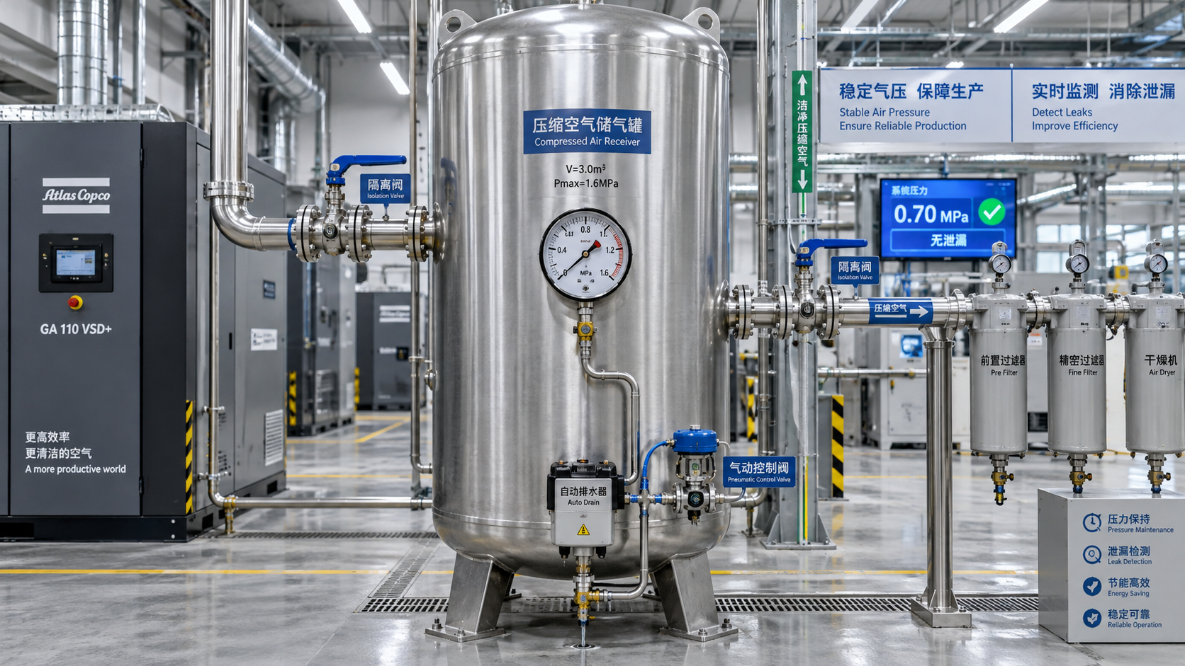
An overnight pressure drop is not automatically evidence of a major air leak. It can result from normal cooling after compressor shutdown, intentional venting through control devices, leakage across isolation points, or internal bypassing in valves, cylinders, and compressor components. The important distinction is whether the pressure loss is proportional to temperature change and stored-air volume, or whether compressed air is escaping from a part of the system that should remain sealed.
A receiver charged near the end of a working shift can show a lower gauge pressure the next morning even when no air has left the vessel. If the air and receiver cool overnight, pressure falls because temperature falls. Under the ideal-gas relationship, a drop from 35°C to 15°C can reduce a 7 bar(g) reading by roughly 0.4 bar, depending on the actual absolute pressure and temperatures involved. That is very different from a system falling from normal operating pressure to zero, or losing several bar while ambient conditions remain stable.
The practical question behind “Why does a pneumatic system lose pressure overnight?” is therefore not simply where a leak might be. It is which part of the air system is losing pressure, how quickly it happens, and whether that pressure loss is expected by design.
Pressure decay has several different signatures
The pattern of the loss often identifies the fault category before any component is dismantled. A stable, gradual fall that stops at a certain pressure points to a different issue than a receiver that fully depressurizes, or an isolated machine circuit that empties while the main air header remains charged.
A pressure gauge alone does not establish air consumption. It reports pressure at one point, not the mass of air remaining in the complete system. Gauge location, closed valves, trapped volumes, regulator settings, and non-return valves can all make one gauge appear healthy while another section is losing air.
Cooling is often mistaken for leakage
Compressed air leaves a compressor hot. The receiver, distribution pipework, and machine components also retain heat during operation. Once production stops, the enclosed air approaches ambient temperature. Since the air volume is essentially fixed in a closed receiver, pressure falls as temperature drops.
For a meaningful comparison, pressure readings should be taken after the system has stabilized thermally. A reading immediately after compressor shutdown is not comparable with one taken the next morning in a cooler building. This is especially relevant where the receiver is located near a compressor room, a furnace area, or equipment that generates substantial heat during the day.
Cooling cannot explain a system that reaches zero gauge pressure unless a vent or leak also exists. It also cannot explain a local circuit losing pressure when a separate, similarly exposed receiver remains stable. Treat temperature as a correction factor, not as a convenient explanation for significant or accelerating pressure decay.
External leaks: common, visible in theory, frequently missed in practice
External leakage is the most direct source of overnight pressure loss. The difficult part is that many leaks become audible only when the plant is quiet, while others are too small, shielded, or intermittent to hear. A fitting behind a machine guard, a pinhole in flexible tubing, or a damaged thread seal may release little air during an individual production cycle but empty a small isolated volume over several hours.
Common leakage points include:
- Push-in fittings with scratched, oval, or poorly cut tubing;
- Threaded adapters sealed with unsuitable materials or overtightened into damaged ports;
- Quick couplings whose internal seals no longer close fully;
- Manual drain valves left partially open;
- Automatic condensate drains contaminated by oil, rust, or debris;
- Receiver drain connections and pressure-gauge fittings;
- Flexible hoses exposed to abrasion, bending, heat, weld spatter, or chemical attack;
- Safety relief valves that fail to reseat after lifting or that are contaminated at the seat.
Condensate drains deserve special attention. An electronic or float-operated drain is designed to discharge water without wasting compressed air, but a fouled sealing surface can leave it passing air continuously. Conversely, a manual drain used as a routine shortcut may simply have been left cracked open. Because drains are often installed low on a receiver or filter bowl, their leakage may not be obvious during a quick visual inspection.
Leak-detection fluid remains useful for localized checks on accessible fittings. A proper ultrasonic detector is more effective for larger systems, concealed pipework, and noisy production areas. It detects the high-frequency sound generated by turbulent air escaping through a restriction, including leaks beyond normal hearing range. The method is valuable, but it should be used with a test plan; scanning every accessible fitting without isolating system sections can lead to long inspections and uncertain conclusions.
Not every “leak” is external: internal bypassing can empty a circuit
Internal leakage is often more consequential than a hissing fitting because it can also cause erratic machine behavior. Air may move from a pressurized chamber to an exhaust port, to another circuit, or back toward the supply without appearing outside the component.
A pneumatic cylinder is a familiar example. Worn piston seals can allow air to pass from the pressurized side of the piston to the opposite chamber. If that opposite chamber is connected through a directional valve to exhaust, the cylinder circuit slowly loses pressure. Depending on the load and mechanical arrangement, the rod may creep, settle, or remain in position while the gauge decays. A stationary actuator does not prove that its seals are sound.
Directional control valves can leak internally across spool lands or poppet seats. Contamination, corrosion, inadequate filtration, incompatible lubricants, and seal wear can all prevent complete sealing. A valve with an exhaust silencer may conceal the sound of a slow internal discharge. Removing or temporarily monitoring the silencer during a controlled test can reveal whether air is escaping through an exhaust path that should be closed.
Pressure regulators create another diagnostic trap. A standard relieving regulator is intended to vent downstream pressure when its set point is reduced or when downstream pressure rises above the set value. That function may be correct, but it means the downstream circuit may not retain pressure after shutdown in the way an installer expects. A non-relieving regulator behaves differently, and neither type should be selected solely on the assumption that it will serve as a shutoff valve.
Check valves and pilot-operated check valves also need to be distinguished. A simple check valve prevents reverse flow in one direction, but it does not lock a cylinder against internal leakage through a directional valve or cylinder piston. A pilot-operated check valve can lock an actuator port under defined conditions, yet its performance depends on correct installation, pilot pressure, cleanliness, and seal condition. Treating these components as interchangeable leads to misleading overnight tests.
Shutdown logic may be deliberately releasing air
Many machines are designed to exhaust selected pneumatic circuits when electrical power is removed, an emergency-stop condition is triggered, or a safety function changes state. This can protect personnel, prevent unexpected restart, release clamping force where required by the process, or return equipment to a defined condition. In such systems, loss of downstream pressure after shutdown is not a defect; failure to lose pressure may be the more serious concern.
The same applies to compressor controls. Some compressor packages unload or blow down internal pressure after stopping to reduce restart load. That function should not be confused with a leak in the plant receiver. The relevant question is whether the blowdown occurs only within the compressor discharge arrangement or whether it is also depressurizing the receiver and distribution network. A correctly installed minimum-pressure valve, check valve, and receiver arrangement should isolate parts of the system according to the equipment design.
Before treating overnight pressure retention as a reliability target, verify what the machine’s pneumatic schematic and risk-control design require. Holding pressure in an actuator that must be made safe on shutdown can create a different operational hazard. Pressure retention, machine safety, and restart behavior must be considered together.
Isolation testing separates the problem faster than random component replacement
The most useful diagnostic method is to divide the system into volumes and record how each volume behaves. Start with a stable initial condition: stop air production, allow the receiver and air to cool if temperature is a known variable, and note pressure at a defined time. Close the isolation valve between the receiver and the plant header. If the receiver then holds pressure while the header falls, the loss is downstream. If the receiver itself falls, concentrate on the receiver, drain, gauge connection, safety valve, and compressor-side isolation components.
Repeat the approach at major branches. Isolate individual machines, then compare the isolated machine circuit with its supply branch. Where practical and safe, close local shutoff valves at the machine inlet. A branch that stays pressurized when its machine valve is closed but falls when it is opened directs attention to valves, actuators, fittings, and auxiliaries inside the machine envelope.
Test conditions must be documented. Record initial gauge pressure, final pressure, elapsed time, approximate ambient temperature, valve positions, compressor status, and whether electrical control power remains on. Without that information, two overnight observations may not be comparable. A solenoid valve energized overnight behaves differently from the same valve de-energized, and a temperature swing can distort a borderline result.
Where pressure gauges have low resolution or questionable calibration, temporary calibrated gauges or electronic pressure logging provide a clearer decay profile. The value of logging is not merely better accuracy. The curve can show whether pressure drops linearly, falls quickly then stabilizes, begins only after a timed event, or changes with control-state transitions. Those patterns narrow the likely mechanism.
Compressor-side faults are possible, but the receiver boundary matters
If the system loses pressure after compressor shutdown, it is tempting to blame the compressor. In many installations, however, the compressor is separated from the receiver by a check valve. A leaking compressor discharge check valve can permit receiver air to flow back toward the compressor package. Depending on the configuration, the air may then escape through an unload valve, intake path, or another component not intended to see reverse pressure.
This fault is especially plausible when a receiver loses pressure but accessible downstream branches have been isolated and tested. Signs can include air movement or leakage at the compressor after shutdown, repeated pressure changes around the discharge line, or an unloader that appears to vent beyond its normal brief blowdown period. The diagnosis should account for the exact compressor and dryer arrangement rather than assuming every compressor line uses the same layout.
Air dryers, filters, oil-water separators, and condensate management equipment can also introduce leakage points. A fault in this equipment may be upstream or downstream of the receiver, changing which storage volume is affected. Piping diagrams should therefore show actual valve and component locations, not only nominal airflow direction.
Why overnight pressure loss matters beyond the gauge reading
Stored air lost during shutdown has to be replaced when production restarts. That can increase compressor run time, delay pressure recovery, and expose an already marginal compressor to higher demand at shift start. A slow leak may also disguise a more important maintenance issue: water accumulation, deteriorating tubing, valve contamination, or cylinder seals near the end of useful service.
For equipment that depends on retained pressure for gripping, positioning, or controlled restart, the effect is functional as well as economic. Yet preserving pressure should not be treated as a universal requirement. The correct target is that every circuit behaves as intended: safety-related circuits vent when required, stored-energy sections are controlled, and circuits that must remain charged do so within the limits defined by their design.
The strongest maintenance decision is based on the boundary of the pressure loss, its time profile, and the shutdown state of the controls. A pressure drop caused by cooling needs no repair. A drain valve passing air needs correction. A valve or cylinder leaking internally may require a different level of intervention because it can affect machine performance even when total air loss appears modest. Separating those conditions prevents both wasted troubleshooting effort and the more expensive mistake of accepting a genuine fault as “normal overnight loss.”
Related News
- RACC2026 Opens in Hangzhou, Bringing International Buyers to Refrigeration SuppliersTime : Oct 23, 2026
- How to Size an Air Compressor for Pneumatic Tools by CFM, PSI, and Duty CycleTime : Oct 10, 2026
- Why Does a Pneumatic System Lose Pressure Overnight?Time : Oct 19, 2026