
How to Select Pneumatic Control Components for Reliable Automation Systems

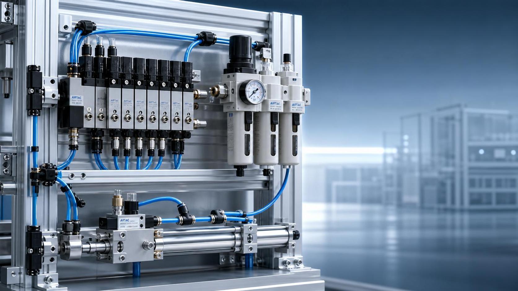
Selecting the right pneumatic control components is one of the most important decisions in automation design because component choice directly affects uptime, cycle consistency, energy use, and maintenance workload.
For technical evaluators, the best selection process is not about choosing the highest specification on paper. It is about matching valves, cylinders, regulators, air preparation units, and fittings to the real operating conditions.
This means evaluating pressure stability, response speed, load profile, environmental exposure, installation limits, and service expectations together rather than reviewing each component in isolation.
When these factors are aligned early, pneumatic systems are easier to commission, more predictable in production, and less likely to suffer from leakage, premature wear, control instability, or avoidable replacement costs.
This guide explains how to select pneumatic control components for reliable automation systems, with practical criteria that help technical teams compare options and make defensible decisions.
What Technical Evaluators Should Prioritize First
When engineers or technical assessment teams review pneumatic control components, their first concern is usually not product variety. It is whether the system will deliver stable motion and repeatable control under actual plant conditions.
That is why early evaluation should focus on application requirements: required force, stroke, cycle rate, control logic, air quality, ambient temperature, duty cycle, and acceptable downtime risk.
A component may look suitable by catalog rating, yet still perform poorly if its response time, flow capacity, sealing material, or mounting arrangement does not fit the machine.
In practice, reliability depends on how well the complete air path works as a system. A fast valve cannot compensate for undersized tubing, poor filtration, pressure drop, or an incorrectly selected actuator.
Technical evaluators should therefore judge components using total system performance criteria, not individual specifications viewed separately. This approach reduces hidden incompatibilities that often appear only during commissioning or long-term operation.
Start With the Application: Motion, Load, and Cycle Demands
The most effective selection process begins with a clear application profile. Before comparing brands or models, define exactly what the pneumatic system must do during each operating cycle.
Key questions include whether the actuator must clamp, push, lift, index, eject, or position a part. Each motion type creates different requirements for speed control, force margin, and stopping behavior.
Load analysis is equally important. Technical teams should calculate not only nominal load, but also friction, shock, side loading, acceleration, orientation, and any variation caused by product changes or process fluctuations.
Cycle frequency also matters. High-cycle automation lines place different demands on valve durability, heat generation, seal wear, and air consumption than low-frequency manual or semi-automatic equipment.
If the application requires precise speed consistency, quick directional changes, or synchronized motion between stations, component tolerances and control response become more critical than basic actuation capability alone.
A well-documented application profile helps evaluators avoid a common mistake: selecting pneumatic control components that can operate the machine in theory, but cannot support reliable performance over time.
How to Choose Pneumatic Valves for Reliable Control
Pneumatic valves are central to control behavior because they determine how compressed air is directed, exhausted, and regulated throughout the machine. Poor valve selection is a frequent cause of slow response and unstable motion.
Technical evaluators should begin with valve function: 2-way, 3-way, 5-way, or proportional control depending on whether the task involves simple on-off action, directional control, or adjustable output.
Flow capacity is one of the most important selection criteria. If the valve is undersized, the cylinder may fail to reach the required speed, and pressure losses may reduce usable force at the actuator.
Response time should be reviewed against the machine cycle target. Fast equipment, pick-and-place units, and indexing systems typically need valves with quick switching characteristics and consistent repeatability.
Voltage compatibility, manual override options, manifold installation, and control integration with PLC architecture also affect practicality in real industrial systems. These factors influence wiring complexity, maintenance access, and future expansion.
For harsh or contaminated environments, valve sealing materials and enclosure design deserve careful review. Dust, oil mist, humidity, and temperature extremes can shorten service life if the valve is not built for those conditions.
When comparing valve options, technical evaluators should ask a practical question: will this valve still switch cleanly and consistently after millions of cycles in the intended operating environment?
Selecting Cylinders: Force Is Only One Part of the Decision
Air cylinders are often selected mainly by bore size and stroke, but reliable automation requires a broader review. Force output matters, yet guiding stability, cushioning, mounting geometry, and speed performance matter just as much.
The first step is calculating required thrust or pull force at the actual operating pressure, with an appropriate safety margin. This margin should account for friction losses, pressure fluctuations, and wear over time.
Stroke length must fit the machine motion without unnecessary travel. Overlong stroke can increase cycle time, create alignment issues, and waste compressed air in repetitive applications.
Mounting style should match the load path. If side loading or off-center force is present, a standard cylinder may wear quickly unless external guides or a guided actuator design are used.
Cushioning is another practical consideration. Adjustable cushions or shock management features can reduce end-of-stroke impact, improving component life and minimizing vibration transferred into the machine structure.
In applications requiring position feedback, magnetic piston compatibility for sensors may be essential. This affects not only control logic, but also installation convenience and fault monitoring capability.
For compact automation cells, space constraints may favor short-body cylinders, rodless cylinders, or integrated slide units. The best cylinder is not the biggest one; it is the one that delivers stable motion in the available footprint.
Pressure Regulators, FRLs, and Air Quality Are Often Undervalued
Many pneumatic reliability problems are blamed on valves or cylinders when the actual root cause is unstable pressure or poor air quality. This is why air preparation should never be treated as a secondary accessory.
Pressure regulators must provide stable downstream pressure across expected flow variation. If pressure drifts during demand spikes, actuator force and speed consistency will suffer even when other components are correctly sized.
Filter selection should match contamination risk and equipment sensitivity. Particles, moisture, and oil carryover can damage seals, clog valve passages, and accelerate wear across the entire pneumatic system.
Lubrication requirements also need review. Some pneumatic control components are designed for non-lube operation, while others may require controlled lubrication for long-term performance. Mixing assumptions can lead to maintenance errors.
FRL units should be selected for flow capacity, pressure range, bowl material suitability, drain type, and service accessibility. A technically correct FRL that is difficult to inspect or maintain can still create operational problems.
For evaluators, the key takeaway is simple: the reliability of pneumatic control components depends heavily on the quality and consistency of the compressed air feeding them.
Do Not Ignore Fittings, Tubing, and Flow Path Losses
In many automation projects, fittings and tubing are treated as low-value commodities. In reality, these items have a direct impact on pressure drop, leakage risk, response time, and installation durability.
Tubing diameter should be selected based on flow demand, run length, and acceptable pressure loss. Tubing that is too small can restrict performance even when valves and actuators are properly chosen.
Fitting quality also matters because repeated vibration, temperature changes, and maintenance handling can lead to loosening or leakage. Small leaks may appear minor but create long-term energy waste and unstable operation.
Material compatibility is another consideration. Chemical exposure, heat, abrasion, and bending stress can all shorten tubing life if the wrong material is specified.
Technical evaluators should review the entire air path from compressor supply to end actuator, looking for restrictions, unnecessary bends, oversized distances, and connection points that could become failure sources.
A reliable pneumatic system is not built only from major branded components. It also depends on the integrity of the smaller connection elements that support airflow and sealing performance.
How to Evaluate Compatibility Across the Full Automation System
Component selection should support system-level compatibility, not just local functionality. A valve, cylinder, or regulator that performs well individually may still create integration problems within the full machine architecture.
Technical evaluators should confirm pressure range alignment, thread standards, mounting interfaces, electrical signals, communication requirements, and sensor compatibility before final approval.
Dimensional compatibility is especially important when replacing existing pneumatic control components in retrofit projects. Small differences in port orientation or mounting pattern can increase redesign time and installation cost.
Control compatibility also matters. Solenoid power requirements, connector types, diagnostic features, and IO integration should be checked against the control cabinet and maintenance practices already used in the plant.
For multinational manufacturing environments, standardization can reduce spare-parts complexity and simplify technician training. Choosing components that fit existing platform standards often improves lifecycle efficiency more than chasing minor initial price savings.
Reliability Means Looking Beyond Purchase Price
Technical evaluators are often asked to compare suppliers on cost, but initial unit price should never be the only selection driver. The true cost of pneumatic control components includes energy use, service life, replacement frequency, and downtime impact.
For example, a cheaper valve with inconsistent switching performance may increase scrap, reduce line speed, or require more frequent intervention. Those costs quickly exceed any initial purchasing advantage.
Likewise, leakage, excess air consumption, and poor regulator stability can raise operating expenses over the life of the equipment. In high-volume production, compressed air inefficiency becomes a meaningful cost issue.
Maintenance accessibility should also be part of value assessment. Components that are easier to inspect, replace, or standardize across multiple lines can reduce mean time to repair and improve plant responsiveness.
A sound evaluation process should therefore include total cost of ownership, not just component price. This gives procurement and engineering teams a more realistic basis for comparing options.
Questions to Ask Suppliers Before Final Selection
Supplier comparison becomes more useful when technical teams ask application-specific questions rather than requesting only catalogs and quotations. The quality of supplier support can directly affect selection accuracy.
Useful questions include expected cycle life under stated conditions, recommended air quality class, response time under load, seal material suitability, spare-parts availability, and known failure modes in similar applications.
Evaluators should also ask whether sizing tools, test data, CAD files, compliance documents, and replacement guidance are available. These resources can significantly reduce engineering effort and implementation risk.
For critical automation systems, it is worth confirming local service capability, lead time stability, and part continuity. A technically acceptable component may still be a poor choice if supply support is weak.
The best suppliers do more than sell pneumatic control components. They help validate the application, identify sizing risks, and support long-term reliability planning.
A Practical Selection Framework for Technical Evaluation
To make decisions more consistent, technical evaluators can use a simple framework built around application fit, control performance, environmental suitability, integration compatibility, and lifecycle economics.
First, define the motion and load requirements in measurable terms. Second, confirm valve flow, cylinder force, regulator stability, and tubing capacity against those requirements.
Third, review environmental factors such as dust, washdown exposure, temperature, vibration, and maintenance access. Fourth, verify mechanical and electrical compatibility with the full automation system.
Finally, compare suppliers based on reliability evidence, support capability, spare-part strategy, and total cost of ownership rather than price alone.
This structured method helps teams select pneumatic control components with fewer assumptions, better documentation, and stronger justification across engineering and procurement discussions.
Conclusion
Selecting pneumatic control components for reliable automation systems requires more than matching catalog specifications. The real goal is to build a stable, efficient, maintainable system that performs consistently under actual operating conditions.
For technical evaluators, the strongest decisions come from reviewing application demands, airflow behavior, component compatibility, air quality requirements, and lifecycle cost as one connected system.
When valves, cylinders, regulators, fittings, and air preparation units are selected with that system view, automation performance becomes easier to predict and sustain.
In industrial environments where uptime, repeatability, and maintenance efficiency matter, thoughtful pneumatic component selection is not a minor design step. It is a core reliability decision.
Related News