
Automotive Fastener Assembly Automation: Integrating Torque Control and Traceability

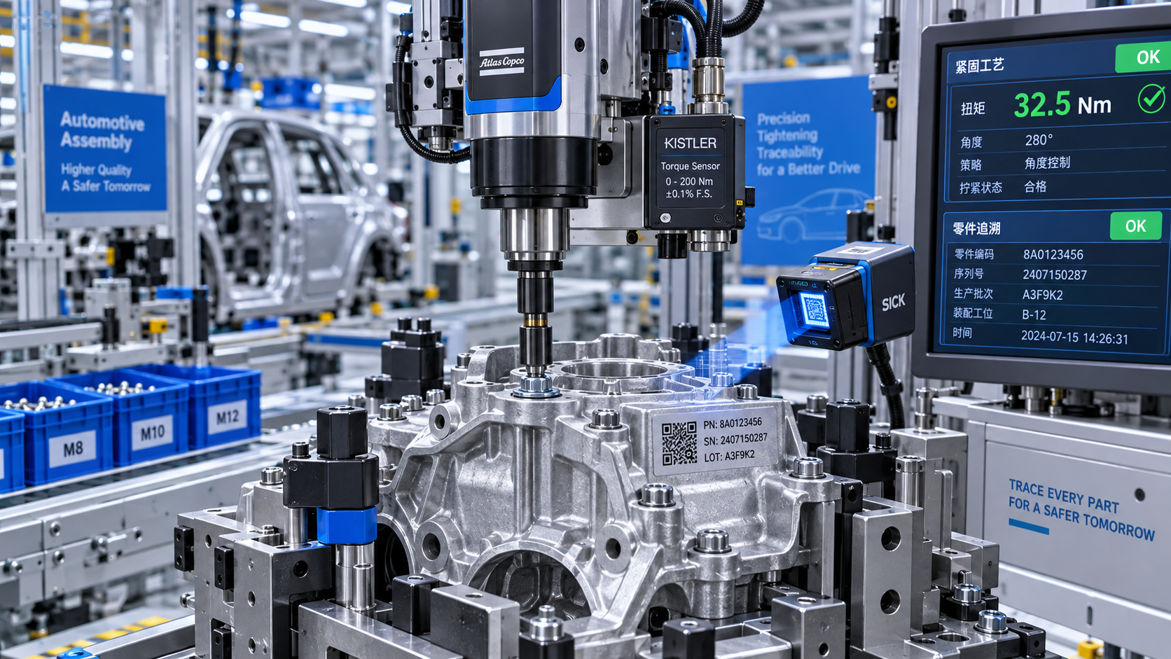
Automotive Fastener Assembly Automation: Integrating Torque Control and Traceability
A missed tightening defect can turn a production milestone into costly rework, a launch delay, or a field failure. For engineering project leaders, automotive fastener assembly automation is therefore more than a cycle-time improvement: torque control and traceability have to work together. Controlled tightening, joint-specific acceptance criteria, and part-linked fastening records help teams detect process deviations and investigate quality problems. The practical challenge is aligning tooling, station controls, and production data without creating a line that is difficult to recover when something goes wrong.
A tightening controller can report a passing result while the station associates it with the wrong assembly. Equally, a database can hold a complete record of a fastening operation that used the wrong recipe. Neither is an acceptable outcome. The project needs to establish not only how each joint will be tightened, but also how the line will prove that the correct operation happened on the correct part.
Start with the joint, not the robot
Before selecting a spindle or screw feeder, define the fastening requirements for each joint family. A bracket attached to a rigid steel structure behaves differently from a cover tightened against a gasket. Thread-forming screws, coated bolts, prevailing-torque fasteners, and bolts entering aluminum threads also require different process assumptions.
The distinction matters because torque is not a direct measurement of clamp load. Friction at the threads and bearing surface influences the relationship between applied torque and bolt tension. A process may reach its torque target despite cross-threading, contamination, or a bolt bottoming in a blind hole. Conversely, changing a coating or lubrication condition can alter preload even when the recorded torque remains unchanged.
Create a joint specification that includes the approved fastener, mating materials, thread engagement, seating condition, tightening sequence, and acceptance strategy. Where preload is critical, engineering validation may require methods beyond production torque measurement. Do not let the automation supplier infer these requirements from a drawing that only shows a nominal torque.
Joint access deserves the same attention. A robot may reach the screw location in simulation but struggle with socket alignment, reaction forces, or surrounding cables on a populated assembly. Check the actual production configuration, including tolerances and service access, before freezing the station layout.
Choose a tightening strategy that exposes likely defects
Transducerized electric tightening systems are often appropriate when programmable control, torque-angle monitoring, and detailed result collection are required. That does not mean every automotive joint needs the same equipment. Tool selection should follow joint risk, access, cycle requirements, and the evidence the quality plan requires.
For some joints, torque control with angle monitoring provides useful checks on rundown and seating behavior. Other joints may use an approved torque-plus-angle strategy after a defined threshold. The threshold, speed transitions, and acceptance windows must be established through joint testing; copying parameters from a superficially similar assembly is a weak shortcut.
Consider a screw securing a housing cover. An unexpectedly short rotation before reaching final torque could indicate an obstruction or premature seating. Excessive rotation could suggest stripped threads or a missing component. These are diagnostic clues, not universal rules. Normal variation must be characterized before limits can reliably distinguish acceptable assemblies from defects.
Keep representative torque-angle curves during development. Final values alone can hide abnormal rundown behavior. For multi-spindle stations, also check how simultaneous tightening affects seating and load distribution. A faster sequence is not necessarily an acceptable substitute for the sequence approved by product engineering.
Make part identity part of the control sequence
Traceability should begin before the spindle starts. The station must establish the assembly identity, confirm the product variant, and select the authorized tightening recipe. Scanning a barcode is only one step: controls must also prevent a stale scan or a reused carrier association from authorizing work on another part.
A practical sequence is: identify the assembly, verify station eligibility, confirm the recipe, enable fastening, evaluate every required position, store the results, and authorize release. The programmable logic controller (PLC), tightening controller, and manufacturing execution system (MES) need explicit handshakes at the boundaries. “Message sent” is not the same as “record accepted.”
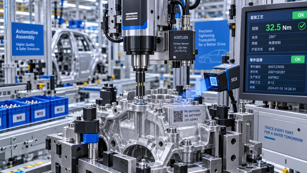
Define what each system owns. The tightening controller normally executes the fastening program and evaluates its measurements. The PLC manages station sequencing and interlocks. The MES or another production system manages product genealogy and operation status. Architectures vary, but responsibility for recipe approval, result persistence, and release permission must never be ambiguous.
Completion should be position-based, not merely count-based. Ten passing tightening events do not prove that ten different bolts were tightened. Robot coordinates, indexed fixtures, position tracking, or controlled tool guidance can help prevent a repeated operation from filling the record of a missed position.
Capture enough context to reconstruct the operation
A useful fastening record links the assembly identifier and joint position to the tool or spindle, recipe revision, measured torque and angle, result status, timestamp, and attempt identifier. Rework records should retain their relationship to the original failure rather than replacing it with a clean pass.
Fastener lot information can support investigations where the supply chain and handling process preserve that link. Bulk feeding makes lot boundaries harder to maintain, especially when hoppers are topped up. If lot-level traceability is required, design replenishment and changeover controls around it; software cannot reconstruct a physical association that was never maintained.
Design exception handling before production starts
Normal-cycle demonstrations rarely reveal the hardest integration problems. Ask what happens when the network disconnects after tightening, a spindle faults halfway through the sequence, or an operator removes a part before its record is committed. These conditions belong in the station specification, not in an informal recovery instruction written during launch.
- Failed tightening: retain the failure, block normal release, and route the assembly through an approved disposition process.
- Lost communication: distinguish between no tightening result, a result awaiting upload, and a stored result awaiting acknowledgment.
- Power interruption: recover the assembly identity and operation state before permitting further fastening.
- Recipe mismatch: inhibit operation rather than allowing an operator to select an approximate substitute.
Automatic retries need particular care. Repeatedly driving a questionable fastener until it passes can damage threads or conceal the original fault. Whether a retry is permissible depends on the joint, fastener reuse restrictions, and validated repair method. Some failures require removal, inspection, or replacement rather than another tightening attempt.
For offline operation, define local buffering, storage capacity, synchronization rules, and release conditions. Unique event identifiers help prevent duplicate records when messages are resent. The allowable offline mode should follow product risk and customer requirements—not a blanket assumption that every communications fault must either stop the line or be ignored.
Validate the fastening process and the data path separately
Tool calibration is necessary, but it does not establish that the production joint is acceptable. Validation should examine actual joint behavior across representative variation: fastener lots, mating-part tolerances, coatings, temperature conditions where relevant, and tool wear. Measurement uncertainty and the suitability of the test equipment also affect how results should be interpreted.
Challenge the process with controlled fault conditions where safe and technically appropriate. Examples include a wrong-length fastener, a missing washer, an intentionally incorrect recipe, or an interrupted rundown. Determine which faults the tightening signature detects and which require separate controls, such as component-presence sensing or fastener verification.
Then test traceability independently. Swap carrier identities, repeat a scan, interrupt the data connection, and restart the station between operations. Confirm that the released assembly has the complete, correct record and that incomplete work cannot inherit a previous part’s status. A passing tightening study does not prove the genealogy system is reliable.
Include these challenges in factory and site acceptance plans. Assign each test an expected response and an owner for corrective action. Otherwise, mechanical installation can appear complete while software exceptions remain unresolved until production pressure makes changes much harder.
Protect cycle time without weakening the evidence
Fastening cycle time includes feeding, approach, engagement, rundown, final tightening, withdrawal, and data handling. Increasing spindle speed addresses only part of that sequence and may create engagement problems. Unstable feeding or poor access can consume more time than the controlled tightening phase.
When evaluating automotive fastener assembly automation, separate essential control functions from data that can be transferred asynchronously. The station may need immediate result evaluation and release authorization, while larger curve files can potentially upload later under controlled buffering. This is an architecture decision, not permission to discard evidence when the network is busy.
Specify data retention and retrieval requirements early. Quality engineers need searchable records by assembly, joint, time range, and recipe revision—not just an archive of files. Protect recipe changes with access controls and revision history, and establish how tool replacement or controller updates affect validated settings.
The Global Hardware & Tooling Network (GHTN) covers fasteners, industrial tools, electrical components, and pneumatic products. That cross-category perspective is useful here: a controlled tightening spindle cannot compensate for inconsistent screws, unreliable feeding, weak fixture clamping, or poorly integrated controls. Review those interfaces together rather than treating the tightening tool as the entire solution.
Before equipment approval, require a demonstrated chain from assembly identification to joint execution, stored evidence, and controlled release. Include a failed tightening and a communications interruption in that demonstration. If the team cannot explain how both are recovered without losing identity or overwriting history, the integration is not ready for production.
Related News
- Greening components or lower cost materials: which wins long termTime : Apr 29, 2026
- FES: China Fastener Exports Reach $9.65 Billion in First Nine Months of 2026Time : Oct 31, 2026
- China’s Fastener Exports Reach $8.182 Billion in January–September 2026Time : Oct 30, 2026