
Panel Fastener Automation: Preventing Misfeeds and Panel Damage During Assembly

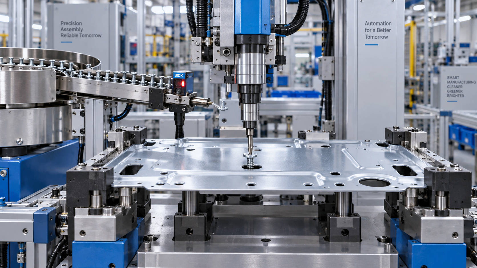
A fastener jam and a damaged panel can begin with the same fault: a component reaches the assembly point in the wrong position, and the machine continues its stroke. Increasing feeder output or insertion force may keep some cycles moving, but it can also turn an intermittent feeding problem into scratched finishes, distorted holes, cracked panels, or unreliable joints.
Effective panel fastener automation requires a verified handoff between feeding, positioning, and installation. Before applying installation load, the machine should establish that one correctly oriented fastener is available, the panel is located and supported, and the tool can approach the joint correctly. Technical evaluation should focus on how the system proves those conditions and responds when they are absent.
Trace the fault to the point where control is lost
“Misfeed” is too broad a diagnosis to guide corrective action. A feeder may fail to release a part, release two parts, deliver one in the wrong orientation, or deliver it correctly only for the tooling to lose it during movement. Each failure requires a different safeguard. A sensor at the feeder outlet cannot confirm that a fastener remains securely held at the installation head.
Separate the process into observable stages: bulk storage, orientation, singulation, transfer, tool retention, approach, and installation. Record where the first abnormal condition appears. If a fastener is already inverted at the transfer inlet, investigate orientation and rejection. If it arrives correctly but shifts during approach, examine retention, tool acceleration, and clearance around the panel.
Fastener geometry determines which feeding methods are realistic. Screws, rivets, spring clips, captive fasteners, and press-in components behave differently in tracks and transfer mechanisms. Clips may interlock; flanged components may overlap; asymmetric parts may require positive orientation control. An arrangement that works for one fastener family may need substantially different tooling for another.
For pneumatic transfer, assess the relationship between fastener shape, tube clearance, routing, and delivery conditions. Tight bends, abrupt transitions, and unsuitable clearances can create unstable travel or trapping points. Excessive transfer energy can cause rebound or damage at the receiving tool. Parts that cannot travel predictably through a tube may justify a track-fed, tray-fed, or pick-and-place approach.
Inspect the incoming fasteners as part of this diagnosis. Burrs, damaged threads, dimensional variation, coating buildup, and contamination can affect both feeding and installation. If failures cluster around particular production lots, changing machine settings alone may hide a component-quality problem. The evaluation should establish which incoming characteristics the equipment can accommodate and which require rejection.
A useful fault record connects the observed symptom to its earliest detectable cause:
- No fastener at the tool: distinguish an empty supply, failed singulation, blocked transfer, and loss during movement.
- Two fasteners delivered: examine escapement geometry, overlapping parts, and whether sensing can distinguish one part from two.
- Correct part, wrong orientation: check orientation control through the entire transfer path, including the receiving nest.
- Fastener present but installation rejected: investigate panel alignment, hole condition, tool retention, and joint compatibility before adjusting force.
Make fastener delivery a verified sequence
Reliable feeding depends on controlled singulation and a stable receiving position. The escapement should isolate one component while restraining the next. Track and nest geometry should guide the fastener without creating unnecessary opportunities to wedge, overlap, or rotate. Access for cleaning and jam removal also matters: a feed path that is difficult to inspect can make diagnosis slow and maintenance inconsistent.
Sensor selection should follow the failure mode. A basic presence sensor may detect metal near the tooling while accepting an incorrectly seated part. Where orientation or seating matters, the system may need separate checks, a mechanical feature that excludes incorrect presentation, or vision inspection. Reflective coatings, small features, accumulated debris, and restricted viewing angles can affect detection, so sensing must be evaluated with representative production components.
The control sequence should require confirmation at the relevant handoff. For example, release a fastener only when the receiving tool is ready; confirm delivery before moving toward the panel; verify panel location before enabling installation; and check the installation result before releasing the assembly. A timer can define when a confirmation is overdue, but elapsed time does not prove that the physical event occurred.
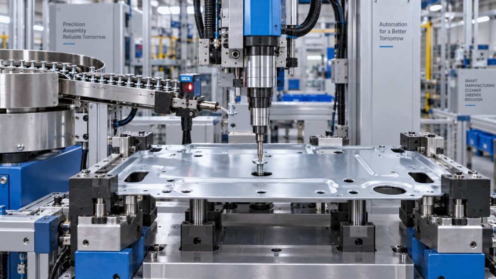
Fault recovery needs equally explicit logic. If delivery fails, the machine should establish whether the transfer path and receiving nest are empty before sending another part. An automatic retry without that check can produce a double feed. Where a partially delivered fastener cannot be reliably detected or removed automatically, controlled intervention is preferable to repeated attempts.
Ask how the equipment behaves during low supply, replenishment, restart, and changeover. These transitions can disturb part orientation or leave the controller’s assumed state different from the physical state. Restart should re-establish the conditions needed for a safe cycle, especially after a jam has been cleared manually.
Buffering can reduce interruptions caused by variation in feeder output, but it also introduces more locations where parts can accumulate or lose orientation. The useful question is whether the buffer preserves controlled presentation and exposes faults clearly. Additional inventory inside the machine provides little benefit if operators cannot identify where delivery has stopped.
Control panel support, alignment, and installation load together
Panel damage is often attributed to excessive force, although the load may be acting through an unsuitable support arrangement. A thin sheet can deflect before a fastener seats. A coated panel can become marked against a hard locating surface. A plastic panel can crack when a local load combines with insufficient edge distance or an incompatible fastener geometry. Reducing force alone may leave the joint incomplete.
Begin with the joint’s approved installation conditions. Establish the permitted panel material, thickness range, hole geometry, edge distance, and fastener specification. Press-in and self-clinching components require particular attention to material compatibility and the specified hole and thickness conditions. Automation cannot compensate reliably for a joint outside the fastener’s application limits.
The fixture should establish repeatable location while supporting the area that carries the installation load. Support positioned too far from the joint can allow bending; support that obstructs the fastener’s exit or forming action can prevent correct installation. Where an anvil or backing tool is required, its geometry and alignment belong in the process evaluation alongside the installation head.
Clamping also deserves scrutiny. Insufficient clamping allows movement, while excessive clamping can distort the panel or mark its finish. A warped panel forced flat in the fixture may appear well aligned during installation and shift after release. Evaluate the finished joint in the released condition, particularly when flatness, gaps, or cosmetic appearance affect acceptance.
Locating from a distant panel edge may leave the tool misaligned with the actual hole because of accumulated dimensional variation. Where feasible, reference features close to the fastening location or measure the local feature before installation. Compliance can help accommodate small positioning errors, but its travel and stiffness must be controlled. Otherwise, the tool may follow an incorrect path without producing a clear fault.
Installation monitoring must match the fastening mechanism. For a press-in component, force versus displacement can reveal early obstruction, unexpected resistance, or an abnormal seating position. For threaded fasteners, torque and angle can help distinguish stages of engagement and tightening. Rivet installation requires monitoring appropriate to the setting method. One generic “force reached” signal cannot establish acceptable installation across these processes.
Monitoring limits should be developed from acceptable joints and representative defects. An early force rise may indicate misalignment or a blocked hole; unusually low resistance may indicate an oversized hole or missing engagement. These are diagnostic possibilities, not universal signatures. Overlapping signals require additional evidence, such as seating-height measurement or inspection of the completed joint.
A staged approach can reduce avoidable damage: move rapidly through verified clear space, slow near the panel, establish controlled contact, and then perform installation within defined limits. The machine should stop or reject when the response falls outside the accepted envelope. Raising force or extending travel to overcome unexplained resistance can conceal a damaged hole or an incorrectly presented fastener.
Cosmetic protection needs its own acceptance criteria. Tool contact, loose fasteners, trapped debris, and panel movement can scratch or indent a surface even when the joint passes mechanical checks. Assess contact materials for marking, wear, and contamination, and ensure that replaceable pads or protective elements do not introduce unacceptable positioning variation as they age.
Validate the operating range and the recovery behavior
A demonstration with selected parts establishes feasibility. Production acceptance requires evidence across the variation the line is expected to encounter. Include representative panel thicknesses, permitted hole-position variation, relevant coatings, and fasteners from more than one lot. For flexible or uneven panels, include acceptable parts that challenge the fixture’s ability to locate and support them.
Define acceptance before the trial. Separate feed reliability, installation quality, panel appearance, and recovery performance so that a strong result in one area does not obscure failure in another. Record rejected cycles and operator interventions as well as completed assemblies. A station can achieve an attractive cycle time while transferring substantial inspection and recovery work to operators.
Useful validation criteria include:
- Delivery: one correctly presented fastener reaches the tool, with faults detected before installation begins.
- Joint quality: seating, retention, or other specified functional properties meet the application’s requirements.
- Panel condition: distortion, cracks, burr formation, and surface marks remain within agreed limits.
- Recovery: a cleared fault does not leave an extra fastener, an uncertain panel state, or an unintended second installation attempt.
Introduce controlled faults during evaluation: missing fasteners, wrong orientation where physically possible, an improperly located panel, and representative hole defects. The objective is to demonstrate that the machine detects meaningful abnormalities before damage occurs and handles them predictably. Deliberate fault trials should use an agreed procedure that protects personnel and equipment.
Include refill, changeover, jam clearance, and restart in the acceptance trial. Review the cycle records available to technicians: delivery confirmations, installation curves, fault codes, and relevant measurements should make it possible to distinguish a feeding issue from a joint or fixture issue. Useful diagnostics shorten the path from a rejected assembly to a justified corrective action.
When comparing systems, ask each supplier to demonstrate the same panel and fastener variation, the same acceptance limits, and the same recovery events. The decisive evidence is whether the equipment maintains control through those conditions and stops when it cannot establish an acceptable assembly. That evidence provides a firmer basis for selection than a fast cycle demonstrated on a small set of ideal parts.
Related News
- Greening components or lower cost materials: which wins long termTime : Apr 29, 2026
- FES: China Fastener Exports Reach $9.65 Billion in First Nine Months of 2026Time : Oct 31, 2026
- China’s Fastener Exports Reach $8.182 Billion in January–September 2026Time : Oct 30, 2026