
Why Do Rivets Crack During Installation?

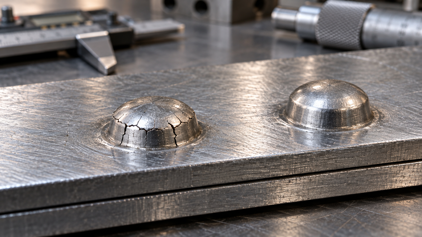
Rivets crack during installation when the deformation needed to form the joint exceeds what the rivet material can tolerate. The immediate cause may be excessive upsetting, an unsuitable material condition, incorrect rivet dimensions, poor hole preparation, or a setting tool that loads the rivet unevenly. Several of these conditions can occur together, so a cracked head alone does not prove that the rivet is defective or that the tool force is too high.
The most useful starting point is to identify which part cracked, when the crack appeared, and whether the damage follows a particular rivet lot, joint configuration, or installation station. Also distinguish unintended cracking from features designed into the fastener: some blind rivets form separate legs during setting, and a mandrel breaking at its intended break point is part of normal installation.
What does the crack location tell you?
Crack location helps narrow the investigation, although appearance alone rarely establishes the root cause. A solid rivet’s formed head, a blind rivet’s expanding body, and the surrounding sheet undergo different loading conditions. Treating all three as the same failure can lead to an ineffective adjustment.
- Cracks around the edge of a solid rivet’s formed head: Investigate excessive deformation, unsuitable material hardness or condition, excessive protruding length, and the shape of the forming tool.
- A crack at the junction between the head and shank: Check for angled loading, poor seating, interference with the hole entrance, inadequate support, or a pre-existing manufacturing discontinuity.
- A split in a blind rivet body: Verify whether that rivet design intentionally splits during setting. If it does not, examine grip range, hole dimensions, body material, and setting-tool compatibility.
- A crack in the sheet beside the rivet: Investigate the parent material, edge distance, hole condition, countersink geometry, and local installation loads. Replacing the rivet alone may leave the underlying problem unresolved.
Inspect several affected joints and several apparently sound joints from the same production run. Look at both accessible sides before removing fasteners. Removal can introduce additional damage and obscure the original failure pattern, especially in thin sheet or soft materials.
Can excessive setting force cause rivets to crack?
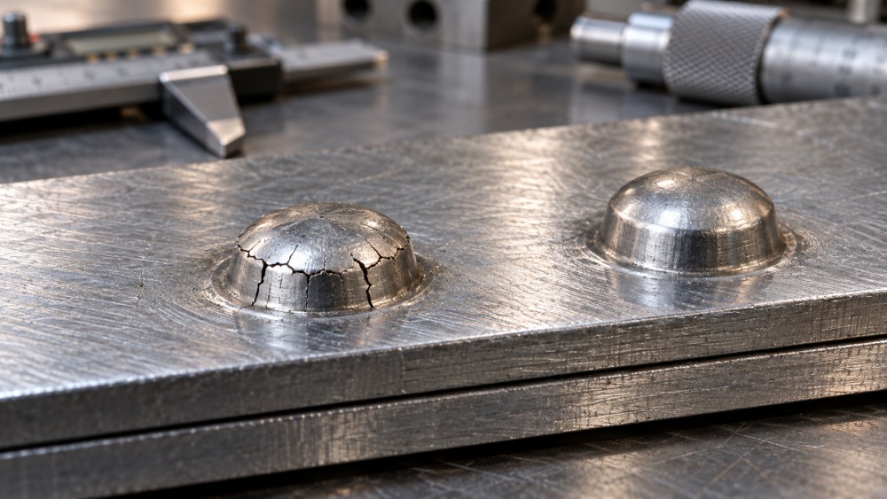
Yes. A rivet needs enough deformation to fill and clamp the joint as intended, but excessive deformation can stretch the material beyond its available ductility. In solid riveting, continued upsetting after the required head geometry has formed can flatten the head excessively and produce edge cracking. With impact tools, unnecessary additional blows can continue working an already formed head.
Force is only part of the explanation. Tool travel, impact duration, alignment, support, and die geometry determine how that force reaches the rivet. A worn or unsuitable die can concentrate strain in one area even when the machine’s nominal setting has not changed. An unsupported assembly can move during installation, producing bending or an uneven formed head.
Blind rivet tools require a different diagnosis. Setting depends on the interaction between the rivet body, mandrel, nosepiece, and pulling mechanism. A higher air-pressure setting does not translate directly into a known clamping force at the joint. A mismatched nosepiece, worn jaws, or an incompatible tool can disrupt the setting sequence. Where the equipment controls force or stroke, use settings established for the specific fastener and application.
Simply reducing pressure until visible cracks disappear is an incomplete correction. The resulting joint may be underformed, loose, or improperly seated. Evaluate cracking together with the required formed geometry, head seating, sheet contact, and any application-specific acceptance criteria.
Why do material and hardness matter?
Riveting depends on plastic deformation. The rivet must be strong enough for service while retaining enough ductility to form without fracturing. A material selected only for high tensile strength may be unsuitable for the intended installation process.
Two rivets with similar dimensions and surface appearance can behave differently if their alloy, temper, heat treatment, or manufacturing history differs. Excessive hardness can reduce forming tolerance. Prior cold work can also leave less capacity for further deformation. Surface laps, seams, or other manufacturing discontinuities may open as the head or body expands.
For rivets whose specifications require controlled heat treatment, storage, or installation timing, those conditions belong in the investigation. Such requirements are specific to the material and fastener specification; they should not be generalized to every aluminum or steel rivet.
A concentration of failures in one production lot makes a material or manufacturing issue plausible, but it does not establish responsibility by itself. That lot may also have been installed on a different shift, through a worn tool, or in a thicker assembly. Compare unused rivets and installation records before drawing a conclusion. Depending on the failure, useful checks may include dimensional inspection, hardness testing, material verification, or metallographic examination.
Changing to a softer rivet can improve formability, but it can also change joint strength, fatigue behavior, or corrosion compatibility. Any substitution should satisfy both installation requirements and the joint’s service requirements.
How do rivet size and grip range contribute?
Incorrect sizing changes how much material must deform and where that deformation occurs. For solid rivets, the length projecting beyond the assembled parts must suit the required formed head and installation method. Excessive projection can encourage buckling, folding, or excessive working during head formation. Insufficient projection can leave an undersized head and tempt the operator to keep driving it without achieving the required geometry.
Blind rivets must match the actual assembled thickness within their specified grip range. Outside that range, the blind-side formation and mandrel break sequence may be incorrect. The result can include poor clamping, irregular body deformation, or splitting, depending on the fastener design. A longer blind rivet is not automatically a safer choice.
Measure the stack as it exists during installation. Include washers, coatings, gaskets, and intermediate layers where applicable, and consider whether compressible materials change thickness under load. A nominal drawing thickness may not represent a joint with assembly gaps or variable components.
Diameter and hole clearance matter as well. An undersized hole can damage the rivet during insertion or constrain its expansion. An oversized hole can allow tilting and uneven support, changing how the fastener deforms. Use the hole limits specified for the selected rivet; one clearance rule will not suit every solid, tubular, and blind rivet design.
Can poor holes or misalignment crack an otherwise suitable rivet?
Yes. Burrs, sharp irregularities, oval holes, and misaligned layers can create concentrated contact and uneven loading. A rivet forced through offset holes may already carry scratches or bending damage before setting begins. During installation, those damaged areas can become crack initiation sites.
Check hole condition through the entire stack. A clean opening on the accessible surface does not reveal a burr trapped between sheets or an offset hole in a lower layer. Hole-making tool wear and movement between components can also produce variation that is easy to miss during a quick visual inspection.
For countersunk joints, verify the countersink dimensions and head seating against the applicable drawing or fastener requirements. An incorrect angle or depth can concentrate contact at the head, reduce local sheet support, or leave the head improperly seated. Increasing installation force to pull an incorrectly seated head into place may aggravate the damage.
Tool alignment deserves the same attention. A forming tool or pulling tool should engage the fastener as intended, with the assembly adequately supported. Restricted access, curved surfaces, or an obstructing flange can force angled tool contact. If cracking occurs only at one position on a component, investigate access and support before changing the rivet material across the entire assembly.
How can you separate a rivet problem from a process problem?
Use controlled comparisons that change one relevant variable at a time. Randomly changing rivet suppliers, tool pressure, and hole size together may produce an acceptable sample while leaving the cause unknown. That makes recurrence harder to prevent.
Start by preserving failed examples, unused rivets from the affected lot, and records of the installation conditions. Record the fastener designation, lot identification, measured stack thickness, hole dimensions, tool and nosepiece identification, and crack location. Photographs taken before removal help preserve evidence.
A practical investigation can then follow this sequence:
- Confirm the fastener: Check material designation, diameter, length or grip range, and any required material condition against the approved specification.
- Measure the joint: Examine hole size, alignment, burrs, stack thickness, gaps, and countersink geometry where relevant.
- Inspect the equipment: Check die or nosepiece compatibility, wear, alignment, support, and the applicable setting controls.
- Run controlled trials: Compare the suspect lot with a previously acceptable lot under the same documented conditions, then isolate tool or joint variables as needed.
- Verify the resulting joint: Assess the required geometry and joint integrity, using sectioning or mechanical evaluation when the application warrants it.
If cracking follows the suspect lot across otherwise comparable, verified setups, the evidence points toward a fastener-related issue. If several lots crack only at one station, the process deserves closer attention. If failures occur only with one assembly thickness or location, joint geometry and tool access become stronger candidates. These patterns guide further examination; they do not replace it.
Is a small crack acceptable, and should the rivet be replaced?
There is no universal acceptable crack size for all riveted joints. Acceptance depends on the fastener type, crack location, application, and governing drawing or specification. A visible opening may be an intended feature of a particular blind rivet, while a similar-looking opening in another design may indicate failure.
An unintended crack can reduce the effective load-bearing section or provide a starting point for fatigue growth. Its significance also depends on whether the joint carries structural loads, experiences vibration, provides sealing, or serves mainly as a locating attachment. Visual appearance alone cannot establish the remaining strength.
Hold affected assemblies for disposition against the applicable acceptance requirements. In structural or otherwise critical work, replacement and repair should follow the approved procedure. Drilling out a rivet carelessly can enlarge the hole or damage the surrounding material, so replacement requires its own process control.
For recurring failures, release the corrected process only after the proposed change produces acceptable joints under representative conditions. A pressure adjustment that works on one accessible sample may fail at a tolerance extreme or a difficult installation position. The useful endpoint is a documented combination of rivet, hole, stack, tooling, and setting conditions that forms the joint reliably—and makes any later departure easier to identify.