
How Can You Reduce Injection Mould Maintenance Downtime?

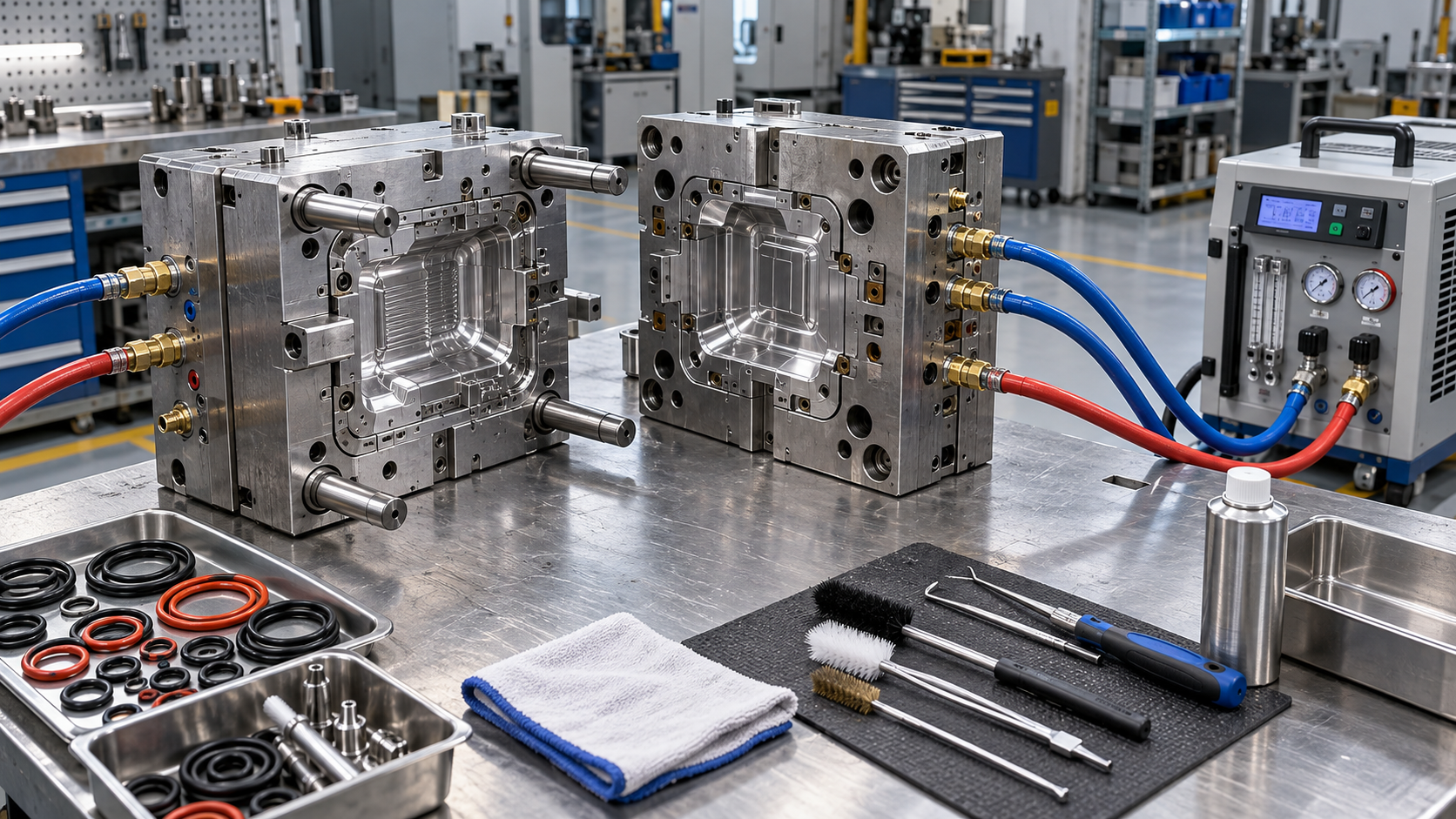
How can I reduce mould maintenance downtime? For injection moulding teams, the answer starts with preventing avoidable failures and making planned servicing easier to execute. Blocked cooling channels, worn ejector pins and overlooked lubrication points can turn small defects into production interruptions. Yet unnecessary dismantling can also waste time and introduce assembly errors.
The practical goal is not simply to service every mould more often. It is to match maintenance to risk, prepare tools and spares before production stops, and verify that repairs have restored reliable operation. The following questions address where downtime usually develops—and how maintenance, production and procurement teams can reduce it together.
Where should you start when mould maintenance takes too long?
Separate the time spent repairing a mould from the time spent waiting. A stoppage recorded as “ejector failure” might include fault diagnosis, waiting for a lifting device, locating a replacement pin, machining it to length, reassembly and first-off inspection. Those delays need different solutions.
Record timestamps for fault detection, safe access, diagnosis, parts availability, repair completion and production release. Include the time needed to achieve stable, accepted parts rather than stopping the clock when the mould returns to the machine.
Review the moulds causing the greatest cumulative production loss. A frequently recurring two-hour interruption may deserve more attention than a rare major overhaul. Prioritise by downtime, recurrence, quality impact and the availability of alternative tooling—not repair cost alone.
Should preventive maintenance follow a calendar or a cycle count?
Use cycle-based preventive maintenance as the starting point for wear-related tasks, then adjust it for operating conditions and elapsed time. Shot counts reflect mechanical use more directly than calendar intervals, but they do not capture every deterioration mechanism.
A mould processing glass-filled resin may need wear inspections sooner than one running an unfilled material. Corrosive processing by-products, frequent colour changes, high operating temperatures and long storage periods introduce different maintenance demands.
Begin with the mould maker’s recommendations and your own service history. Extend intervals only when inspection evidence supports the change. Shorten them when deterioration appears before the planned service point.
Which warning signs justify intervention before a breakdown?
Useful condition monitoring does not always require a complex sensor installation. Repeatable observations, recorded against a stable process, can reveal deterioration early enough to schedule work between production runs.
- Cooling: declining flow, unusual pressure drop, changing temperature behaviour or longer cooling time under comparable conditions.
- Ejection: hesitation, abnormal noise, sticking parts or rising ejection force where it can be measured reliably.
- Part quality: progressive flash, drag marks, localised burns or cavity-specific dimensional drift.
- Hot runner performance: repeated zone alarms, unstable temperatures or electrical readings outside supplier-approved limits.
None of these signals proves that the mould is at fault. Flash can result from process or clamping conditions; sticking may involve resin, cooling or release geometry. Use the symptom to trigger diagnosis, not an automatic teardown. Unnecessary dismantling creates its own downtime and damage risk.
How can cleaning reduce downtime without damaging the tool?
Standardise cleaning by surface and contamination type. A polished cavity, textured insert, vent land and cooling circuit should not share one aggressive cleaning method. Specify approved products, tools, contact times, drying steps and inspection criteria for each area.
Pay particular attention to vents and parting surfaces. Deposits can restrict gas escape or prevent correct closure, but scraping or uncontrolled polishing may alter geometry. Clean to the drawing or established maintenance standard; do not deepen a vent simply because burn marks have appeared.
For cooling circuits, establish flow readings under comparable supply conditions. Where practical, check individual circuits rather than relying only on a manifold reading. Investigate restrictions, leaks, water quality and connector problems before choosing a treatment.
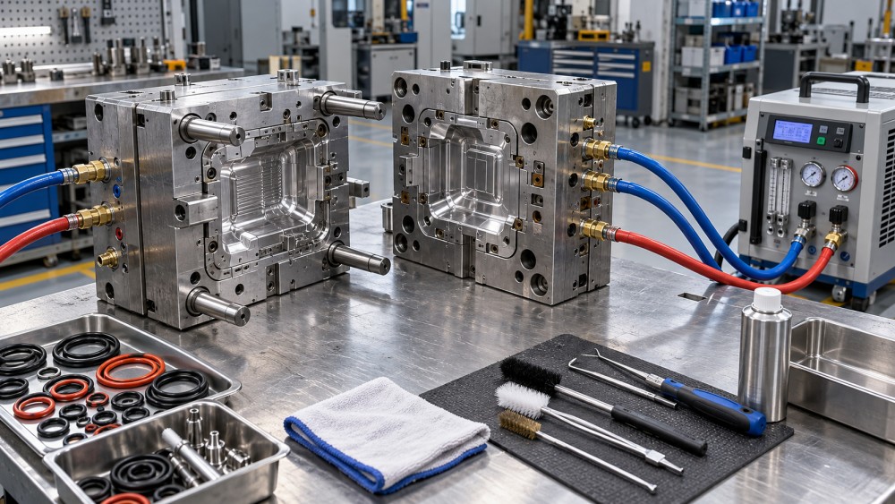
Chemical descaling requires compatibility checks for mould materials, seals and connected equipment, followed by the specified flushing and protection procedure. Aggressive treatment can create leaks or corrosion. After cleaning, verify that flow and leak performance meet the tool’s acceptance criteria.
What should a faster planned service look like?
A short service begins before the press stops. Review the previous repair record, confirm the job scope, reserve the work area and prepare replacement components. If a spare needs grinding, fitting or supplier confirmation, resolve that before removing the mould whenever possible.
A practical service pack should contain:
- The mould identification, current drawings and relevant assembly photographs.
- A task-specific checklist covering inspection points, clearances and approved lubricants.
- Prepared parts, seals, fasteners and any special assembly tools.
- Required tightening specifications and functional test criteria.
- A restart checklist and clearly assigned production-release responsibilities.
Stage external work separately from work requiring shutdown. Documentation, spare verification and tool preparation can usually happen while production continues. Internal cleaning and repair cannot.
Use appropriate energy isolation, pressure release, thermal precautions and rated lifting equipment before intervention. Moulds may retain hydraulic, pneumatic, electrical or thermal hazards after the machine stops. Faster maintenance must never depend on bypassing guarding or working beneath an unsupported load.
Which spare parts are worth keeping on site?
Stock parts according to failure likelihood, replacement lead time and production consequence. A low-cost custom ejector pin can justify local stock if its absence stops a critical tool. An expensive component available quickly through a reliable source may need a different arrangement.
Typical candidates include ejector pins and sleeves, return pins, compatible seals, selected springs, water connectors, heater bands, thermocouples and tool-specific hot runner components. The exact list should follow the mould’s bill of materials and failure history.
“In stock” must mean ready and correct. Verify dimensions, material, hardness, coating, electrical rating and compatibility as applicable. Keep custom parts traceable to the mould and drawing revision. For hot runner systems, check the specified component and connection details rather than assuming similar-looking parts are interchangeable.
Purchasing teams should also confirm whether a spare is finished, semi-finished or still requires fitting. Discovering an unfinished replacement during a stoppage defeats much of the benefit of holding stock.
Can mould design changes and quicker changeovers help?
Yes, especially when the same servicing difficulty appears repeatedly. Accessible lubrication points, replaceable wear inserts, serviceable cooling connections and clearly marked assemblies can reduce maintenance effort. Modular components may shorten repair time, provided alignment, sealing and part quality remain controlled.
For existing moulds, use repair history to justify modifications. A recurring damaged connector may need better protection or relocation, not another identical replacement. Repeated slide wear may require investigation of alignment, loading, lubrication delivery or operating temperature.
Changeover improvements also matter because maintenance downtime often extends into removal and installation. Standardised connection layouts, labelled hoses, prepared handling equipment and documented setup values reduce avoidable searching and reconnection errors.
Quick couplings and quick-clamping systems still require suitable pressure, temperature and load ratings, along with machine compatibility and validation. A connection that saves installation time but restricts cooling flow is not an improvement.
Why do the same faults return after a successful repair?
Often, the repair replaced the damaged component without correcting the condition that damaged it. A broken ejector pin could be the result of misalignment, inadequate support, excessive resistance or an incorrect operating sequence. Replacing the pin alone leaves the cause in place.
For repeat faults, preserve the evidence: photographs, the failed component, cavity identification, process settings and the circumstances immediately before failure. Compare actual dimensions and movement with drawings and known-good operation.
Record the suspected mechanism separately from the confirmed cause. Then assign a corrective action, an owner and a verification point. “Monitor next run” is only useful if the record states what to measure and when to review it.
Include production operators in the review. Their observation that sticking began after a cooling interruption may be more useful than a repair note saying only “pin replaced”.
How do you restart production without creating another stoppage?
Build release checks into the maintenance job rather than treating them as optional work after reassembly. Depending on the intervention, checks may cover component movement, ejector return, slide sequencing, cooling leaks, hot runner electrical condition and protective devices.
Use the approved setup procedure and controlled operating conditions to confirm safe function. Qualified personnel should perform electrical tests using methods suitable for the installed components.
Production release must also address the parts. Verify the relevant dimensions, appearance and cavity-to-cavity consistency, with particular attention to features affected by the repair. Keep startup scrap and stabilisation time visible in the downtime record.
A mould that closes correctly but produces drifting dimensions has not completed a successful maintenance cycle. Equally, acceptable first-off parts do not prove that a repaired cooling leak or intermittent movement fault has been resolved.
Which measures show whether downtime is genuinely falling?
Track a small set of measures consistently rather than collecting data nobody reviews:
- Unplanned mould downtime: hours lost by mould and failure category.
- Time between failures: measured in operating hours or cycles, using a consistent definition.
- Restoration time: elapsed time from stoppage to accepted, stable production.
- Repeat faults: recurrence of the same failure mechanism after repair.
- Maintenance-related startup loss: time and scrap required after servicing.
Separate planned maintenance from unplanned failures. An initial increase in scheduled servicing can be worthwhile if breakdowns and total production loss decline. Compare results across similar materials, production volumes and operating conditions so that changes in workload do not disguise the outcome.
If you need one action to begin this week, review the last several stoppages on a critical mould. Identify the largest avoidable delay, prepare the missing spare or procedure, and set a measurable acceptance check for the next service. Reducing mould maintenance downtime is usually the result of removing these specific obstacles—not simply asking technicians to work faster.
Related News
- Micron-level precision in molds: when tighter tolerances backfireTime : Apr 29, 2026
- North American Moldmaker Rankings: Top Five Sales Fall 9.3%, Smaller Firms Hold SteadyTime : Oct 27, 2026
- Which Mould Steel Is Best for High-Volume Injection Moulding?Time : Oct 29, 2026