
What Causes Flash After an Injection Mold Is Shipped?

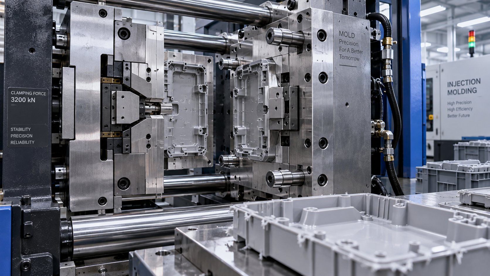
Flash that appears only after an injection mold has been shipped is rarely caused by one isolated event. More often, the mold was accepted under a limited trial condition, then exposed to a different machine, resin, setup method, maintenance standard, or production schedule. The critical distinction is whether the mold is actually unable to seal, or whether the receiving process is forcing material through an otherwise acceptable parting line.
That distinction matters because the visible defect can look identical. A thin fin of plastic at the parting line, around inserts, ejector pins, slides, vents, or gates may be blamed on “poor mold quality.” Yet reducing clamp force, changing resin drying, correcting machine parallelism, or lowering peak cavity pressure can eliminate flash without any tooling modification. Conversely, a mold that requires unusually conservative settings to remain flash-free may have a genuine fit, support, venting, or steel-condition problem that was not revealed during pre-shipment trials.
Why a mold can pass trials and flash at the receiving plant
A mold trial confirms performance only within the conditions used for that trial. It does not automatically prove that the mold will behave the same way on every press or with every approved resin grade. The most useful comparison is not between “supplier fault” and “molder fault,” but between the original proven process window and the actual production window after delivery.
Key variables often change at shipment:
- the injection molding machine and its platen condition;
- available clamp force and the way it is calculated or monitored;
- barrel size, screw design, nozzle geometry, and check-ring response;
- resin supplier, grade, batch behavior, regrind content, moisture condition, or color concentrate;
- melt temperature, mold temperature, injection speed, transfer point, holding pressure, and cooling time;
- installation practices, locating-ring fit, clamping setup, water connections, and handling after unpacking.
Flash therefore needs to be investigated as a pressure-versus-sealing problem. It occurs when cavity pressure overcomes the mold’s ability to hold the shutoff surfaces together. That loss of sealing may be caused by excessive pressure, insufficient clamping, misalignment, physical damage, wear, trapped contamination, or a combination of these conditions.
The first comparison: true mold flash versus process-induced flash
A reliable diagnosis starts with the defect location and its repeatability. Flash appearing uniformly along the main parting line has a different meaning from flash localized at one corner, around a slide, beside an insert, or at vent locations.
The comparison is not absolute. A weak local shutoff can remain invisible at low cavity pressure and flash only after the processor raises fill speed or pack pressure to solve another issue, such as a short shot or sink mark. But the defect pattern tells the investigation where to begin. Randomly polishing the parting line before process data are reviewed can remove evidence and may make future fitting work harder.
Clamping force is often misunderstood after mold transfer
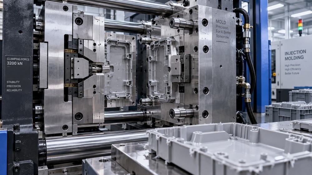
Insufficient clamp force is a familiar explanation for flash, but the machine’s rated tonnage is not the same as usable clamping force at the mold. Effective clamping depends on machine condition, platen parallelism, tie-bar loading, mold size, mold centering, and the projected area of the molded part and runner system. A press may have enough nominal tonnage but still apply uneven force to the mold.
A large mold mounted off-center can load the platens unevenly. A mold with poor support beneath the cavity area can allow local plate deflection even when the clamp setting appears adequate. In multi-cavity production, the cavity nearest a region of lower effective support may show flash first. This can be misread as a cavity machining issue when the real problem is how the mold is being clamped.
Higher clamp force is not automatically the correct remedy. If flashing stops only when the machine is operated near its practical limit, the operation may be masking excessive cavity pressure or a mold support issue. Running at a very high clamp setting can accelerate platen wear, stress the mold structure, and make it difficult to maintain a stable process. The better question is whether the mold remains flash-free within a reasonable, documented process window on a suitable press.
Machine compatibility can change the pressure profile
Two molding machines set to the same displayed injection pressure and holding pressure do not necessarily produce the same cavity-pressure history. Hydraulic and electric machines control motion differently; screw diameter affects pressure intensification; check-ring condition affects shot consistency; and response during velocity-to-pressure transfer can vary materially. A mold that was sampled on one press may therefore need its process developed again after installation on another.
Barrel capacity is also relevant. If a small shot is run in an oversized barrel, residence time and melt history can become less stable. If the shot is too large relative to barrel capacity, recovery, melt preparation, and pressure control may become difficult. Neither condition proves that the mold is defective, but both can contribute to pressure variation that exposes a marginal shutoff.
Nozzle contact deserves attention as well. A poor fit between nozzle and sprue bushing can cause leakage, freeze-off behavior, or unstable transfer. It does not usually create parting-line flash directly, but it can lead operators to compensate with hotter melt or higher pressure, creating the conditions that do.
Processing changes that raise cavity pressure
Flash is frequently a downstream symptom of an attempt to correct another molding problem. A short shot may lead to increased injection speed and pressure. Sink marks may lead to higher holding pressure or a longer pack time. Weld-line concerns may lead to a hotter melt or mold. Each adjustment can increase the force trying to separate the mold halves.
The most important comparison is between peak pressure during filling and pressure applied after the cavity is volumetrically full. A part should generally be filled predominantly under velocity control, with transfer occurring before overpacking begins. If transfer is too late, the screw continues to force material into a nearly full cavity at high speed. A sharp pressure rise can open a marginal parting line long before the displayed hold-pressure setting becomes relevant.
Holding pressure can also be excessive in magnitude or duration. Once the gate has frozen, additional pack time cannot improve part weight or compensate for shrinkage; it only adds cycle time. Before gate freeze, excessive packing can flash the mold, especially around vents and movable shutoffs. A practical check is to compare part weight across controlled changes in holding time. If part weight no longer increases, the gate is likely frozen, and further packing should not be needed.
Material temperature is another common difference between trial and production. Higher melt temperature lowers viscosity, allowing resin to enter narrow gaps more easily. It may also increase filling pressure behavior depending on the overall process. Elevated mold temperature can delay freeze-off at the gate and parting line, extending the period in which packing pressure reaches the cavity. These are legitimate processing tools, but they cannot be changed independently without reassessing flash risk.
Resin condition can be as important as resin name
Using the same polymer family does not guarantee the same molding behavior. Grade-to-grade differences in melt flow, filler content, impact modification, flame-retardant package, pigment loading, and shrinkage can shift the process window. A lower-viscosity grade can penetrate small shutoff gaps that a higher-viscosity trial resin did not reveal. Filled grades may change wear behavior over time and can alter venting requirements.
Moisture control matters particularly for hygroscopic materials. Improper drying is more commonly associated with splay, brittleness, molecular degradation, or surface defects than with flash alone. However, unstable material preparation can produce inconsistent viscosity and encourage repeated pressure adjustments. The resulting process instability makes it harder to identify whether flash comes from the resin condition or from an underlying mold issue.
Regrind content requires similar discipline. If regrind is permitted, it should be controlled by the resin supplier’s recommendations and the part’s performance requirements. Uncontrolled blends can shift flow characteristics and obscure the baseline established during mold qualification.
Damage, corrosion, and contamination during shipment or installation
A mold can be mechanically sound when it leaves the tool shop and still arrive with a sealing issue. The vulnerable areas are not limited to the visible cavity surface. Parting lines, slide shutoffs, insert seats, leader pins, bushings, ejector systems, and locating features can all be affected by poor preservation, incorrect lifting, impact during transport, or careless unpacking.
Rust preventive compounds create a particular inspection issue. If preservative is not fully removed from vents, insert seats, or shutoff areas, it can trap debris or prevent components from seating completely. Conversely, aggressive cleaning can remove protective oil from guiding components and expose precision surfaces to corrosion. Fine corrosion marks on a shutoff face may be enough to permit flash under production pressure.
Foreign material is often overlooked because it can be extremely small: hardened resin, polishing compound, packaging debris, metal particles, or residue in a slide pocket. If the flash begins immediately after installation and is concentrated at a movable component or insert, checking full seating and contact surfaces should take priority over changing every process parameter.
Wear-related flash should not be confused with delivery-related flash
If flash emerges only after thousands or millions of cycles, normal wear becomes more credible than shipping damage. Repeated contact at parting surfaces, abrasive filled materials, poor lubrication of slides, inadequate alignment, and high clamp cycling can gradually alter shutoff geometry. Ejector pins and guide components can develop clearance; slides can lose precise positioning; vent lands can erode or be damaged during cleaning.
The timing still matters. A mold delivered as “new” but placed directly into high-volume production may reveal an insufficiently robust design rapidly. A shutoff that works in a short sampling run may not tolerate thermal cycling, production pressures, or abrasive resin. That is different from ordinary long-term wear and should be assessed against the agreed mold specification, approved material, cavity count, machine range, and expected production conditions.
Attempts to solve wear-related flash by increasing clamp tonnage are especially risky. Higher clamp force can temporarily keep the mold closed, but it may increase contact damage at already compromised surfaces. Repair may require restoring steel, re-fitting inserts, correcting slide geometry, replacing pins or guide components, or revising vent design rather than simply changing a machine setting.
What should be compared before deciding who owns the correction
Commercial disputes become less speculative when the receiving plant preserves a clear technical record. The most useful evidence is not a single photograph of a flashed part; it is a comparison of the qualified condition and the production condition.
- Record the resin manufacturer, exact grade, colorant or additive system, drying condition, and regrind policy used during trial and production.
- Compare machine make, clamp capacity, platen dimensions, tie-bar spacing, screw diameter, nozzle arrangement, and any available machine condition records.
- Document actual process settings, including fill time, transfer position, cushion, peak injection pressure, holding profile, mold temperature, and cycle time.
- Map the flash location by cavity and feature: main parting line, gate region, vents, insert perimeter, slide shutoff, or ejector detail.
- Inspect the mold before alteration for contamination, corrosion, witness marks, incomplete slide travel, damaged edges, or uneven contact evidence.
- Review packing and shipping records, installation photographs, lifting points, and any handling event that could have affected alignment.
This comparison also clarifies a frequent contractual weakness: acceptance based only on a short trial. A stronger acceptance record identifies the approved material, machine range, target cycle, cosmetic requirements, critical dimensions, process limits, and any known restrictions. Without those references, a mold may be judged against conditions it was never designed to meet.
A practical sequence for restoring stable molding
Start with a controlled baseline rather than a broad set of simultaneous changes. Confirm that the mold is clean, correctly installed, fully seated, properly lubricated where required, and that slides or inserts return to their closed positions. Verify water flow and temperature control because uneven thermal conditions can distort parts and alter cavity pressure behavior.
Then reduce the process to a conservative condition: lower melt temperature within the resin’s approved range, moderate injection speed, earlier transfer, and reduced holding pressure. If flash disappears, increase settings methodically only as required to meet fill, weight, dimension, and appearance requirements. If flash remains at low-pressure settings and occurs at the same localized feature, a tooling, alignment, or seating issue becomes more likely.
Do not treat venting as a universal explanation. Proper vents allow displaced air to escape; they are not intended to pass molten polymer. Flash at vents can indicate vent depth or damage, but it can also indicate overpacking. The correct repair depends on whether the vent is geometrically too open or whether the process is driving too much pressure into the cavity.
The central lesson is simple: flash after shipment is not proof that shipping caused the defect, nor proof that the receiving process is wrong. It is evidence that the production system has lost its sealing margin. Identifying where that margin was lost—through machine force, pressure settings, resin behavior, mold installation, damage, or wear—is the basis for a durable correction rather than a temporary adjustment.
Related News
- Micron-level precision in molds: when tighter tolerances backfireTime : Apr 29, 2026
- North American Moldmaker Rankings: Top Five Sales Fall 9.3%, Smaller Firms Hold SteadyTime : Oct 27, 2026
- Which Mould Steel Is Best for High-Volume Injection Moulding?Time : Oct 29, 2026