
Cleanroom Pneumatics: Controlling Particles, Lubricants, and Exhaust Air

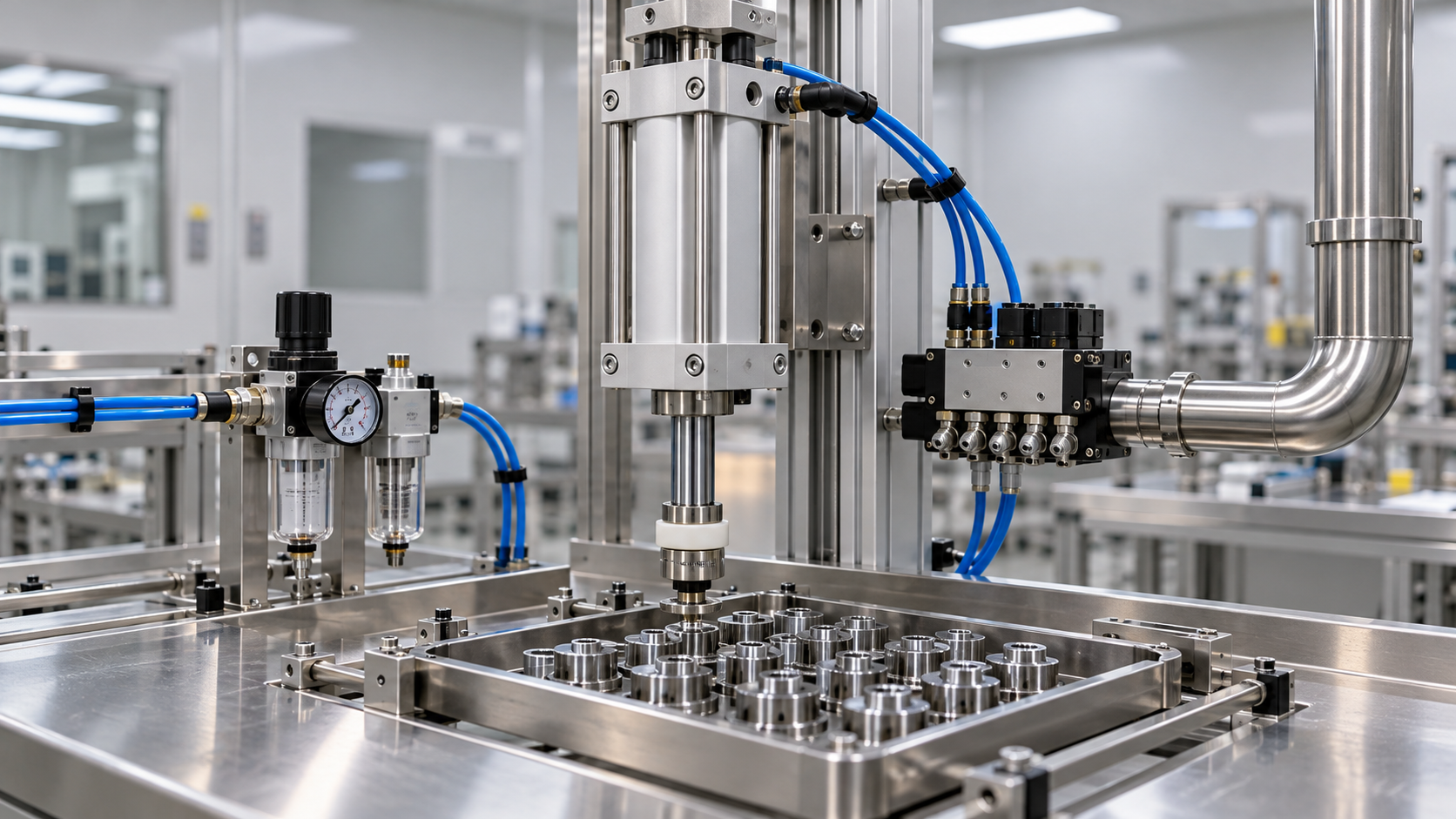
A pneumatic cylinder can arrive with a cleanroom suitability report, run on filtered compressed air, and still contaminate a sensitive process. Rod seals wear, assembly grease migrates, tubing sheds debris, and exhaust jets disturb particles that were previously settled. The difficulty is not simply finding a “clean” component; it is understanding what the installed system releases, where those releases travel, and whether they reach the product.
For technical evaluators seeking all you need to know about pneumatics for clean rooms, the most useful starting point is a system boundary: compressed air generation, distribution, valves, actuators, exhaust routing, and maintenance. Evaluating these together makes supplier comparisons more meaningful and prevents a component-level claim from becoming an unsupported system-level assumption.
Three different cleanliness questions—not one rating
Cleanroom pneumatic specifications often mix together three separate requirements: the cleanliness of the room, the quality of the compressed air, and the contamination emitted by equipment. Each needs its own acceptance criteria.
A statement such as “suitable for ISO Class 5” therefore needs supporting conditions. Ask which particle sizes were assessed, how the equipment operated, where measurements were taken, and whether exhaust was captured. A stationary cylinder and the same cylinder cycling under load are not equivalent test conditions.
For molecular contamination-sensitive applications, such as certain optical or semiconductor processes, ISO 14644-8 may also be relevant. Pharmaceutical applications can introduce additional microbiological and aseptic-processing requirements. Low particle emission, sterility, and chemical compatibility are distinct properties.
Follow the contamination path from supply to product
Picture a small actuator mounted above an exposed assembly. Supply air enters a valve, pressurizes a cylinder chamber, and later exits through the valve’s exhaust port. Meanwhile, the rod moves through a seal directly beside the workpiece. Those two paths—internal airflow and external mechanical motion—create different contamination risks.
Mechanical wear at the point of motion
Rod seals, wipers, guides, and internal bearings experience friction. Wear particles may remain inside the actuator, escape around moving interfaces, or travel with exhaust. Side loading, rod misalignment, excessive speed, and hard end-of-stroke impacts can accelerate wear even when the component was initially suitable.
The external rod also moves between exposed and enclosed surfaces. Deposits on it can be carried toward the seal and later redistributed. A smooth rod surface, suitable seal design, correct alignment, and controlled cushioning matter as much as the cleanliness of incoming air.
Contaminants carried through the air circuit
Compressor oil carryover, condensed water, pipe scale, installation debris, and filter media contamination can enter the pneumatic circuit. Downstream components may add their own residues, so a measurement at the compressor outlet does not establish cleanliness at the machine.
Consider the consequence of a release as well as its quantity. Exhaust directed toward an exposed wafer, sterile container, or adhesive bonding surface may be unacceptable even when the room’s overall airborne particle concentration remains within its specified class.
Lubrication: distinguish oil-free air from lubricant-free equipment
“Oil-free” is not a complete cleanliness specification. An oil-free compressor avoids introducing oil through its compression mechanism, but intake air and downstream equipment can still contribute hydrocarbons. Likewise, a cylinder designed to operate without added airline lubrication may contain factory-applied grease.
For many cleanroom applications, eliminating an airline lubricator is sensible because oil mist can travel through valves and emerge at exhaust points. However, removing a lubricator from an existing system is not automatically safe. Confirm that every affected component is rated for non-lubricated service and check the manufacturer’s guidance on changing lubrication practices.
Factory grease requires a different assessment. Ask about its base chemistry, volatility, migration tendency, compatibility with cleaning agents, and suitability for the process. A food-grade lubricant is not automatically appropriate for semiconductor processing; a low-vapor-pressure lubricant does not automatically meet pharmaceutical requirements.
Completely dry-running designs also involve trade-offs. Depending on construction and duty, reducing lubrication can increase friction, wear, or required actuator size. The practical target is not always “no lubricant anywhere,” but controlled lubricant selection and containment supported by relevant testing.
Specify compressed air where it is actually used
ISO 8573-1 separates particle, water, and oil requirements. Procurement documents should state the required class for each category, the sampling location, and the operating conditions. Avoid a vague instruction such as “provide cleanroom-grade air,” which leaves too much open to interpretation.
Class 0 deserves particular care. It does not mean absolute zero contamination. It requires a defined specification more stringent than Class 1 for the relevant contaminant category. A supplier’s Class 0 claim should identify the contaminant, limit, and test basis.
- Particles: Evaluate distribution-pipe debris, final filtration, and contamination introduced during machine assembly.
- Water: Select a pressure dew point appropriate to the lowest expected distribution and operating temperatures to prevent condensation.
- Oil: Consider liquid oil, aerosols, and vapor. A coalescing filter does not by itself address every form of hydrocarbon contamination.
- Microorganisms: Where relevant, establish separate microbiological requirements and a validated treatment and monitoring approach.
Treatment may combine drying, particulate filtration, coalescing filtration, and adsorption, depending on the incoming air and required result. More filtration is not automatically better: pressure drop can reduce actuator force, encourage higher supply settings, and increase energy consumption.
Verify air quality downstream of the final relevant treatment stage, close to the actual point of use. Where air directly contacts product, define requirements for that contact rather than assuming the surrounding room classification is sufficient.
Exhaust management often determines whether the design works
Clean supply air can become contaminated after passing through a valve or actuator. Exhaust can contain wear particles and lubricant residues, and its velocity can resuspend contamination from nearby surfaces. Treat exhaust as a designed flow path, not an incidental opening.
Remote exhaust needs hydraulic-style attention to resistance
Routing exhaust outside the critical zone can reduce local contamination, particularly when valves are also located remotely. But long tubing, small internal diameters, restrictive silencers, and shared manifolds create backpressure. That changes cylinder speed, available force, cushioning behavior, and sometimes valve operation.
Size exhaust lines for peak flow rather than average consumption. Check simultaneous actuator operation and the possibility of pressure interaction through a common exhaust header. Maintain required separation where one circuit could influence another, and follow valve-specific restrictions on pilot exhaust connections.
Remote discharge must also be coordinated with facility ventilation. Moving contamination outside a mini-environment is not enough if the outlet releases it into another sensitive area or interferes with room pressure control.
Local filtration is not a substitute for verification
Where remote routing is impractical, an exhaust filter may be appropriate. Its retention performance, flow capacity, shedding behavior, and loading characteristics all need review. An ordinary pneumatic silencer should not be assumed to provide validated cleanroom particle control.
Monitor the consequences of loading: rising backpressure can gradually alter machine behavior before anyone notices visible contamination. If a supplier offers vacuum-assisted collection around a rod seal or enclosure, assess capture performance and operating limits rather than assuming suction removes every release.
Compare cylinders, valves, and accessories as an assembly
A cleanroom-oriented actuator can offer reduced particle emission through seal design, controlled lubrication, external surface finish, or dedicated collection ports. Stainless steel construction may support corrosion resistance and cleaning, but material choice alone does not establish low particle generation.
Evaluate the full bill of materials. Tubing, push-in fittings, thread sealants, sensors, mounting hardware, and cable jackets can introduce particles or chemical residues. Exposed threads and crevices complicate cleaning; incompatible cleaning chemicals can embrittle tubing or damage seals.
Valve placement is a trade-off. A remote manifold removes a potential emission source from the work zone, but longer lines add dead volume and affect response. A local valve can improve control while increasing the importance of enclosure, exhaust collection, and accessible cleaning surfaces.
Before comparing prices, request evidence covering:
- Particle-emission test method, particle-size channels, sampling positions, and background conditions.
- Stroke, speed, load, orientation, pressure, cycle count, and exhaust configuration during testing.
- Lubricant identity or relevant compatibility information, plus restrictions on relubrication.
- Permitted cleaning agents, installation procedures, packaging, and replacement-part controls.
- Performance limits for remote exhaust, including allowable backpressure.
A report for a related product family is useful background, but it may not cover the selected bore size, seal option, or duty cycle. Ask suppliers to identify those gaps explicitly.
Qualification must include operation and maintenance
Incoming inspection cannot reveal every contamination mechanism. Establish a baseline, then assess the installed machine during representative operation, including demanding combinations of speed, load, and simultaneous motion. Measure near vulnerable product locations as well as at locations required by the facility’s qualification plan.
Separate background contamination from equipment emissions wherever practical. Include startup, extended cycling, and intervention scenarios. Newly installed equipment may release assembly debris, while worn components may behave differently after extended service. An initial pass does not establish lifetime suitability.
Maintenance belongs in the qualification strategy. Opening a pneumatic circuit, replacing a cylinder, or changing an exhaust filter can introduce debris and residues. Define approved parts, clean handling, capped storage, controlled reassembly, and post-maintenance verification. Avoid uncontrolled blow-down inside the cleanroom.
Useful warning signs include increasing exhaust backpressure, unstable cycle times, rising leakage, visible lubricant migration, and changes in local particle trends. Set inspection and replacement intervals from operating experience and supplier guidance, rather than relying on calendar intervals alone.
The decision is about controlled emissions, not a cleanroom label
Pneumatics can be appropriate in controlled environments when motion-related emissions, air purity, lubricant behavior, and exhaust are managed together. Where those controls become difficult, compare alternatives such as isolated actuation or electric motion—but assess their own wear, lubrication, and thermal effects rather than assuming they are contamination-free.
A defensible specification connects each risk to an acceptance criterion and supporting evidence. Room classification defines the environment; compressed air requirements define the supply; operating tests demonstrate the installed result. Keeping those boundaries clear gives evaluators a sounder basis for selection—and fewer unwelcome surprises after the equipment enters production.
Related News
- Cleanroom Pneumatics: Controlling Particles, Lubricants, and Exhaust AirTime : Nov 02, 2026
- Fast-Cycling vs. Washdown Equipment: Which Pneumatic Cylinder Features Matter?Time : Oct 30, 2026
- Industrial Air Cylinder Uses in Clamping, Material Handling, and PackagingTime : Oct 25, 2026